Re: The Original And Best Whopper ???..........
now THAT'S something that makes sense!
now THAT'S something that makes sense!
mrfeedback said:"The Original WHOPPPER® Sandwich has been doing its thing since 1957. It's a fire-grilled classic and everything you would expect from a great-tasting burger – 1/4 pound of beef, red ripe tomatoes, crisp lettuce, creamy mayonnaise, ketchup, crunchy pickles and onions all on a freshly baked bun. Add extra ketchup and HAVE IT YOUR WAY®."
Lars Clausen said:Just wanted to add the schematic to our solution discussed. So easier to follow.
Sorry the text is in Dansih language, but the schematic should speak for itself.
The resistors ensure that the charging spike is equally distributed over the entire capacitor bank, and also equally discharged from all 4 capacitors to the amplifier.
I will just emphasize one point, so everyone in here can understand, also Fred:Only the positive side of the power supply is shown here on this schematic. There need also be a corresponding negative side of this power supply circuit to make it work properly.
Wouldn't this circuit just increase the ESR of each cap? Then to account for the increased ESR you have to put a high quality bypass cap on the whole network?
Scott
As to the bit about raising the ESR, well, not really, but it raises the net resistance of the power supply, although by an insignificant amount, further mitigated by the small, high quality cap on the output.
More relevant, it raises the resistance seen by HF noise, which might otherwise just 'bounce' past the caps, never even seeing a path to ground, due to the slowness of the caps. Now the HF will at least 'see' a small series resistance, then a fast cap, forming a good low pass filter.
Also, raising the resistance, without affecting the reactance, yields a lower Q factor, which means you are damping power supply resonances.
The slightly raised rise-time also serves to protect the rectifier, as well as reducing noise spewed back onto the mains.
For class A/B amplifiers, where the average power may be significantly lower than the peak power, you might want to use such a supply, and use higher value input resistors (less load on the presumably small transformer, which is sized based on average load), while retaining the low value output resistors, for better transient response.
As to just using two caps, that makes sense, if they are fast enough. Unfortunately, the larger a cap is, the slower it tends to be.
Of course, there are many solutions to this problem. I'll just list a few.
(A) Go with what Lars did, and build a power supply with controlled resonances and better load sharing, using many small, fast caps.
(B) Use a polypropylene cap instead. Unfortunately, they come in small capacities (I've seen none bigger than 330uF), so you would have to use high voltages to exploit their storage capacity, and a switcher to step the voltage down.
(C) Use stages that consume a constant amount of current, such as differential stages (e.g. the Son of Zen or BZLS). These should be indifferent to the high frequency capabilities of the power supply. In fact, slow caps might help the CMRR at high frequencies, as any imbalance tends to be degenerated by the low compliance of the supply.
(D) Use full or partial shunt regulation of your supply, so that your HF response is dependent on the shunt circuitry, rather than the slow caps. For example, use a depletion mode FET from the rail to ground, with a resistor on the gate, and a cap from the rail to the resistor.
(E) Do what Lars did, but parallell hundreds of small caps instead.
(F) Do what Lars did, but switch the resistors for inductors instead. Select the values, including the Q of the inductor, carefully. You must be especially careful of the output, as you don't want ringing from interactions between the smaller, fast cap, and the inductor, during load variation.
(G) Any combination of the above.
(H) Forget about it, and just build an "audiophile" grade switch mode power supply, throwing such concerns as 'efficiency', 'low cost', and 'cool operation' out the window.
Just my 2 cents.
The term 'switching power supply' refers to a different kind of power supplies from what you are used to (those are called 'linear supplies')..
There are a lot of audiophile myths about switching supplies being bad, and if you want to dispel them, go have a listen to some of the high end products from e.g. Linn, that use switching supplies. Theirs are so good they even eliminate any gains from filtering or fancy power cables, which is hard to do, regardless of the kind of supply you use.
Basically, a computer grade supply is bad because it is built from overly cheap components, and designed to save money.
As to how switching works, it depends. The most basic thing is, you chop up the alternating current from the mains into pulses, that are deposited into capacitors as usual. The number of pulses per second, or their energy content, or both, can be shaped in a number of ways, allowing good regulation, and ideal mains loading.
Good results can be achieved through hard work and good engineering. Bad results are easily achieved by cutting corners or bad engineering. Regardless of whether you use switched power supplies, or linear power supplies. The skill threshold for using the switching technology successfully just happens to be a bit higher.
It is simple enough to build hybrid supplies, though, where a transformer, rectifier, and cap, provide a high voltage DC supply, and some transistors, resistors, an inductor, a capacitor, a diode, and a voltage reference (e.g. zener), let you step down the high voltage to a lower, more useful voltage.
Of course, any kind of switching process generates noise, and you have to deal with it. Which is a topic that is common to switched and linear supplies, frequently addressed with large inductors, fast capacitors, regulation, and so forth.
Hope this clarifies.
cowanrg said:could someone simply and plainly explain what a switching power supply is?
Look here: http://henry.fbe.fh-darmstadt.de/smps_e/smps_e.asp
Along those lines........
Spectral audio goes even futher with seperate windings, bridges, and output caps for each output transistor for theIR DMA-360.
http://www.spectralaudio.com/dma360.htm
Spectral audio goes even futher with seperate windings, bridges, and output caps for each output transistor for theIR DMA-360.
http://www.spectralaudio.com/dma360.htm
Attachments
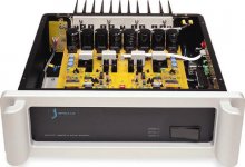
I fail to see how doing everything seperately is going to do significant good, except if they are using seperate transformers, in which case there would be no current sharing issue (the core stores energy, as I recall?). And I read your post as stating that they only use seperate windings.
Their approach fails to lower the Q of any power supply resonance, and might for that matter end up with a higher net resistance from the power supply than what the LC Audio solution achieves.
And Lars only needs one transformer, two bridges, and two decoupling caps, which allows him to put more money into their quality. Also, less mounting work, logistics, etc., means he does not have to spend as much money on things that are not better parts, leaving more money to spend on said better parts. Unless I am mistaken, that decoupling cap is a Mundorf supreme.
Kudos for Spectral being willing to go to such an extreme, though. Now, if they had only spent that effort on something else...
I imagine the mounting costs (labour etc.), and the costs associated with using nonstandard transformers, would easily sum up to what it might cost them to implement a high quality AC shunting supply, and possibly get rid of caps altogether in the process, depending on how constant the load presented to the supply is.
At audio frequencies, what effect had this unequal current?Lars Clausen said:Just wanted to add the schematic to our solution discussed. So easier to follow.
Sorry the text is in Dansih language, but the schematic should speak for itself.
The resistors ensure that the charging spike is equally distributed over the entire capacitor bank, and also equally discharged from all 4 capacitors to the amplifier.
I will just emphasize one point, so everyone in here can understand, also Fred:
mrfeedback said:The biggest lie (whopper) is suggesting that eating those things is good for you !!!.
Eric.
At least they admit it.
I wonder if they were aware of the double meaning of the
word when coming up with that burger name? BTW, I just
looked it up in my Oxford and instead of just listing the two
different meanings they define whopper as "something
unusally big, especially a big lie".
Cobra 2: You are so right!
Also we only use the V4P solution in our Class A amplifier, and multichannel PWM's where large capacitances are absolutely nessescary.
In 2 ch. amplifiers with PWM modules 2 good caps will do better than V4P any day of the week. Practical tests show that a good PWM amplifier of 2 x 250 Watts RMS essentially require only two
2200 uF / 100 V capacitors (yes 2.200 not 22.000) to reach a good sound quality level. So the solution in that case is as you mention a couple of good caps.
A Class A amp can't get enough capacitance, so here we need to use at least 50 - 100.000uF. But unfortunately i have not seen any good capacitors of say 100000uF 50V....
Peranders: If you were to draw a curve of your power supply's impedance at different frequencies, also in the audio region, i think you would 'bump' into the answer. Pun intended ;o)
Lars Clausen said:Nelson: Then consider this setup of the two capacitors in parallel, when you view it as the capacitor's practical equivalent circuit.
As you know every capacitor consist of a capacitive part (obviously), an inductive part and a resistive part (last two from wire leads and internal windings of the aluminum foil). There is also a fourth part a parallel resistor, but it has no significance in this discussion.
When you have one capacitor it will act as a series filter with it's lowest impedance at one specific frequency. But when you parallel two caps, they can interact with each other's internal circuit. Especially if the inductance or capacitance is not exactly matched. (Which they can never be in a real-life scenario).
Consider the possibility that C1 might form a parallel resonance with L2 and vise versa. Might occur if the parallel connection resistors (here 1 milliOhm) are low enough. I think that anyone can see that would be a problem in your amplifier power supply.
In the V4P circuit shown above, the problem is eliminated by breaking the circuits apart into separate series filters.
I can't resist beating on this subject, so I apologize in advance.
Particularly referencing the diagram which was included from the
above (quoted from page 1), the analysis is incomplete. It
neglects the inductance and resistance of the voltage source,
the inductance of the connections between the capacitors,
the effect of the load impedance, the effect of any CLC or CRC
filtering deliberately employed, and the effect of any bypass
caps.
In fact, once you include the inductance between the cap
connections, you can start arguing that you have a C(L+R)C filter,
and in the posting before the one just quoted, maybe 9 poles of
such. I usually go to considerable trouble to make such
supplies.
Certainly high noise current and voltage are going to fly around
in the system after the recifier diode, whether you parallel caps
or not, and I continue to insist that this effect is miniscule by
comparison, and is removed by the same mechanisms that
remove the main ripple effects.
Ripple in still water, when there is no pebble tossed
I believe that the point the guy explaining this to Lars was trying to make is that if attention is not paid to PCB and wiring impedance, the caps can very well have different ripple currents across them. One of the reasons for using multiple capacitors that each individual capacitor is not rated to carry a disproportionate share of the ripple current and that the ripple current is to be divided equally by the number of caps in parallel. This prolongs the life of the capacitors and is just good engineering. I have a feeling that it was the in the context of wiring and PCB impedances that this was presented.
The addition of resistors between transformer and rectifiers is not a bad idea either. It limits the peak current through the transformer reducing saturation and current through the rectifiers which effects reverse recovery time and RFI. the parallel equivalent of four 0.1 ohm resistors is 25 milliohms which is in the range of transformer secondaries impedance for a large transformer. I have seen this technique used elsewhere for audio power supplies.
The point in separate windings, bridges, and filter caps in the Spectral amp is to put the caps close to the output devices to minimize parasitic L and R between the filter caps and output transistors. Keith is one sharpest engineers I have ever met and doesn't do much stuff in the way of gimmicks. I have heard a direct microphone feed through one of the Spectral amps during a recording session in the Mort Meyerson Symphony Hall in Dallas and he must be doing something right...........
A simplified but similar technique is used by Steve McCormack who puts the filter caps next to the output devices.
http://www.mccormackaudio.com/index1.html
- Status
- This old topic is closed. If you want to reopen this topic, contact a moderator using the "Report Post" button.
- Home
- Amplifiers
- Pass Labs
- LC Audio story on current woppling?