Hello,
I just picked up these two items, but cannot find
much information about them. Ideally, I would like
some basic operating instructions, and original
specifications. A couple particular questions -
there are two main outputs,is one pair inverting?
In order for me to get the preamp to work with a
stereo amp I must use the right output from one
set, and the left output from the OTHER set, why?
There are two phono inputs - do they both offer the
same amount of gain, or is one dedicated to MC use
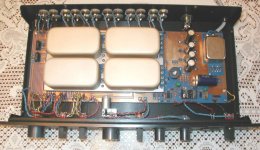
with the M1 unit? The quality of components, and
construction appear to be of very high quality. Are
there any details on the design topology, and components
avaliable? Would this be a good preamp to check over,
and replace any out of spec. items, or should I spend
money on a more current design (coda maybe)?
Finally, this preamp dates from 1977, how long was it
in production, and were very many of them produced?
Lots of questions, I know, but I believe this is a
Nelson Pass designed product, so I hope I came to the
right place!!") Any help would be great,
Any help would be great,
Steve
I just picked up these two items, but cannot find
much information about them. Ideally, I would like
some basic operating instructions, and original
specifications. A couple particular questions -
there are two main outputs,is one pair inverting?
In order for me to get the preamp to work with a
stereo amp I must use the right output from one
set, and the left output from the OTHER set, why?
There are two phono inputs - do they both offer the
same amount of gain, or is one dedicated to MC use
with the M1 unit? The quality of components, and
construction appear to be of very high quality. Are
there any details on the design topology, and components
avaliable? Would this be a good preamp to check over,
and replace any out of spec. items, or should I spend
money on a more current design (coda maybe)?
Finally, this preamp dates from 1977, how long was it
in production, and were very many of them produced?
Lots of questions, I know, but I believe this is a
Nelson Pass designed product, so I hope I came to the
right place!!
Any help would be great,Steve

Actually, it sounds like it has been modified or is broken.
For help and information, I recommend Jon Soderbeg
vintageamp@earthlink.net
For help and information, I recommend Jon Soderbeg
vintageamp@earthlink.net
Thanks for the information, I was unsure
if Jon did work on preamps, so I started here.
The pre. works and sounds good, so I bet since
the outputs are not correct this is probably from
a past service - the filter caps in the power supply
were replaced - I'll bet the output jacks were
removed from the chassis and replaced incorrectly.
Thanks again for the info.
Steve
Just had Jon Soderberg of Vintage Amp go through the NS 10 I have.
Jon advised this was a prototype NS 10, not the standard production NS 10.
Was fully operational when I received it, but being some 28 years in service, decided to send to Jon for a check out and any needed service. Replaced all non film caps and additional work done of the modules. Sounds fabulous, great build quality, as we have come to expect.
Connected to a Threshold 400A power amp. Amazing to me that after 47 years in this hobby, I keep going back to the early Threshold gear. For me there is just something special about this gear, and now when I can afford most high end gear, its become back to the future - Kinda weird in some respects.
Anyway I highly recommend Jon for any and all service work on Threshold products. Great work,price is right, and knows what he is doing. Hard to find today.
I'm very pleased to hear that the NS10 is still working out for
you. The M1 remains a unique circuit that no one seems to
have copied, much like the I/V converter of the D1.
Also, I'm pleased to hear good things about Jon, as we continue
to recommend him for Threshold service issues.
you. The M1 remains a unique circuit that no one seems to
have copied, much like the I/V converter of the D1.
Also, I'm pleased to hear good things about Jon, as we continue
to recommend him for Threshold service issues.
Nelson, hard to believe that someone hasn't ripped off this design, as your designs have been ripped of more times than I can remember in the past 30 years or so.
Jon has worked on several Threshold items for me and have always been most impressed with his work. I recommend him very highly and have sent him many clients.
Forgot to tell Jon to replace the Volume pot. But I can handle that chore. Any ideas on which one to use? I have a Noble 50K around here somewhere, use that or something else?
For me the NS 10 is just magical. Perhaps not everyones cup of tea, but for me and quite a few others it remains after all these years a bench mark pre amp. As the 400A power amp remains a bench mark power amplifier.
Attachments
For me the NS 10 is just magical.
NS 10 is known as the first Threshold preamplifier. I don't know much about Threshold history (but I can ask Jacco
)From several Threshold preamp schematic floating around here, like NS10, Fet10, SL10, I REALLY suspect that NS10 is the best sounding one (even it is the first released).
I make a "back-engineered" NS10 preamp using the schematic provided by NP (no values), and use the first transistor with Jfet (K30), the sound is MMMAAARRRVVVEEELLLOOOUUUSSS.
I think about it for several weeks. Why? It is a single transistor system (not differential), and the more you look at the schematic, you will realize that it is essentially a CFP with gain (like JLH). CFP is considered 1 stage, right? So, it is 1 stage, with good linearity (there is feedback, current feedback-to emitors, very fast), no harmonic canceling. It's hard to have high order harmonics with this approach, but you can get super detailing and very fast response. What else do you want?
lumanauw said:
NS 10 is known as the first Threshold preamplifier. I don't know much about Threshold history (but I can ask Jacco
From several Threshold preamp schematic floating around here, like NS10, Fet10, SL10, I REALLY suspect that NS10 is the best sounding one (even it is the first released).
I make a "back-engineered" NS10 preamp using the schematic provided by NP (no values), and use the first transistor with Jfet (K30), the sound is MMMAAARRRVVVEEELLLOOOUUUSSS.
I think about it for several weeks. Why? It is a single transistor system (not differential), and the more you look at the schematic, you will realize that it is essentially a CFP with gain (like JLH). CFP is considered 1 stage, right? So, it is 1 stage, with good linearity (there is feedback, current feedback-to emitors, very fast), no harmonic canceling. It's hard to have high order harmonics with this approach, but you can get super detailing and very fast response. What else do you want?
hm-I know my sh#t with tubes,just because I put more than just few years in passion for various tube stages and topologies .....but I have not equal knowledge (ie - feel ) with transistors or I just have not enough time to use same approach (reading,lookin' thinkin' , buildin' and tweakin....
) .........can you share that "back-engineered " schmtic with us (me) ?
dumb Choky
If you are a "dumb", then I'm the "dumber"
You got the blind NS10 schematic in your hands?
If you do, then here's what I do.
-First, I use symmetrical power supply, +/-25V with 0 gnd. So, I do not use R5, R6, R7 in the schematic. If you got only single supply 0/50V, then R7=200k, R5=R6=100k, C4=47uF.
- R13=20k potentiometer, for volume adjust. The wiper goes to left of C1 (470nF MKT), R12 is moved after C1. The bottom of VR13 goes to ground via additional 1k resistor, the upper is fed with input.
-The right of C1 connected to voltage divider (R6-R7), thus to R12=1k, and this R12 connects to gate of Q1, or if you got symmetrical supply, you can put the right of C1 with 100k to gnd (0V).
-R12=1k, is placed after the voltage divider (that is after C1) and before the gate of Q1 (2sk30y).
-I also put 470pf WIMA from gate to drain of Q1 (2sk30y).
-R4=10k, Q2=mpsA92, Q3=mpsA42, R8=470ohm, C2=C3=22uF non polar elko. R1=10k, R2=2k2 (makes gain=10k/2k2), R9=2k7 1/2watt.
- put base stopper at base of Q3, I use 1k there.
- R3 is for adjusting DC output, it is about 100k-470k, depends what device you use for Q1. I myself don't mind DC offset at left of C2, I got only 0V5 there, so I don't use R3. Sounds better without R3, even it has DC.
-R10=100ohm, R11=100kohm.
I tried various devices for Q1, MPSA06, MPSA42, 2n5401, BC550C, BC546, they sound differently. The best sound is 2sk30y (you can also buy 2sk30gr suffix).

Hi, Tmblack,
I don't invent the schematic, it is NP who make it. So, I really don't know the values of each component and its main function.
From my backengineering (I don't use SIM, I go straightly to the real thing), it seems R3 is only for determining DC point at output, and in my real cct, it works without R3 at all, but it has slight DC. Sounds better too without R3.
Without R3 : Example Q1=bipolar with VBE=0V6. The current flowing through Q1 is 0V6/R4. I use R4=10k, so the current flowing is 6E-5A. Without R3, this current will flow from emitor of Q1 to R1 then to R9. This means if the base of Q1 is hold at 0V, and R4=R1=10k, then at the output (before C2) it will be -1V2.
I don't invent the schematic, it is NP who make it.
So, I really don't know the values of each component and its main function.From my backengineering (I don't use SIM, I go straightly to the real thing), it seems R3 is only for determining DC point at output, and in my real cct, it works without R3 at all, but it has slight DC. Sounds better too without R3.
Without R3 : Example Q1=bipolar with VBE=0V6. The current flowing through Q1 is 0V6/R4. I use R4=10k, so the current flowing is 6E-5A. Without R3, this current will flow from emitor of Q1 to R1 then to R9. This means if the base of Q1 is hold at 0V, and R4=R1=10k, then at the output (before C2) it will be -1V2.
hehe-just click at button bellow...tmblack said:Hey Choky,
what's your favorite tube preamp design?
I have some 6922 and 6SN7 still in box.
Tom
look for WOT
easily made with one 6922 per channel,with both sections paralleled
unsurpassed type of music presentation,if not anything else ...

Here's the basic NS10 circuit.
Since the M1 is basically the same as the the SL10 MC input
stage, you can see it on the SL10 schematic which is posted
at www.passlabs.com/np
Since the M1 is basically the same as the the SL10 MC input
stage, you can see it on the SL10 schematic which is posted
at www.passlabs.com/np
Attachments
tmblack said:Hi Lumanauw
you are correct, good job at figuring out the values.
I plan on trying it and Choky's preamp.
Tom
EE
like I say-use ECC88 or 6922,both sections in paralel;
Ua around 100V on top of your OPT ( OC3 is pretty handy there,even if I dont know exact current capacity in this moment (little bookie is not near me) so you;ll need maybe even two OC3 per channel ......
I suggest that you use grid stoppers of circa 100 ohms per each grid, both anodes tyed together with ferite bead right at base -as must ;I also always put that bloody 1M resistor from grid to ground,just because I can't trust to any pot to hold grid at gnd potential forever .......
both cathodes tye together and use one mutual resistor in range 43 to 51 ohms ,and you'll be in current range of some 25 to 30 mA per channel ;some 1000 micro/6V sh#ty BG cap or other (choice is yours) across cathode resistor is your choice also
you can also try NiCD (at least 4Ah/1V2 ,NiMH also) in cathode ( as battery charger instead of preamp hehe) but be prepared that some cells are bad for that use-oscillations can arise if you use "bad " accu .....
in final breadboarding try to rotate just secondary leads (rotate-swap, whatever you call it) -just because in one position capacitive parasitics in OPT are smaller than in other position.
loading secondary with some resistor can be usefull also (sonically wise) but that depends solelly of your particular OPT.....
I hope that some of this will help .......
Nelson Pass said:Here's the basic NS10 circuit.
Since the M1 is basically the same as the the SL10 MC input
stage, you can see it on the SL10 schematic which is posted
at www.passlabs.com/np
just rename that *.zip to *.gif
Attachments
- Home
- Amplifiers
- Pass Labs
- Threshold NS-10 and M1 info. wanted