I just can't find anything wrong with the board. Removed the PSU and only thing is the slight hum. Replaced the Q4 but the measurement is still the same.
what I'm missing is - are JFets on pcb , are mosfets connected ?
you need to add few lines of text with measurement , to be sure that we are staying on same track
for now , I'm just confused , almost all the time
what I'm missing is - are JFets on pcb , are mosfets connected ?
you need to add few lines of text with measurement , to be sure that we are staying on same track
for now , I'm just confused , almost all the time
Yes, ZM. The jfet is on the pcb and the mosfets (2 pairs ) are connected. I have changed the bjt Q3 and Q4 . Switch on and the ampere is just like the last time.
Last edited:
something is wrong in your troubleshooting technique ;
- if measurements in post #106 are true ,
- if mosfets are OK,
- if connection to mosfets are as needed,
- if mosfet source resistors are OK ,
- if pcb isn't scorched ,
- if PSU is functional ,
- if wiring is identical to functional channel ..........
.... damn thing need to work .
so - find where is difference vs. functional channel and you'll find the culprit
Normally the +ve current exits via the -ve rail.
Most dual polarity amps do not exactly balance + & - currents and the difference exits via the Power Ground.
A weird wiring error may give a different exit route.
Opamps that do not have a Power Ground, have only power in and power out.
The + & - currents MUST EXACTLY match.
When an input signal is present there will be an output signal. That output signal current MUST come from one, or other, of the supply rails.
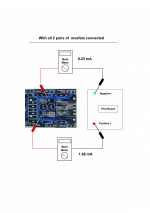
Hi ZM. Thanks. I've learn a lot from you. Should the current consumption be equal on both rails, ie. if the the negative is in the range of 8mA, then the positive should also be around 8mA?
approximately same for both rails - current going from pos to neg rail
posts #102 and #106 are showing proper results
everything after (with mosfets added in circuit ) is just confusing
I can't figure out - is it issue your improper measurement (even if successful in #102) , or something else
it's best to find someone locally to help you , in vivo
Most dual polarity amps do not exactly balance + & - currents and the difference exits via the Power Ground.
Thanks, Andrew. How much is the difference in terms of approximate percentage?
approximately same for both rails - current going from pos to neg rail
For some reasons unknown at this moment, I can't seems to repeat the measurement in post #102 and #106 even when i have removed the mosfet and ground the inputs and output. I ma still getting the approximate 8mA for the negative rail and 1.9mA for the positive rail.
Hi, today I have some time to revisit my Aleph J amp and I decided to changed the isolation pads for the mosfets with some Keratherm I have extra. And the result is astonishing. The measurement before the pads were changed :
R16 = 0.542v
R17 = 0.813v
R18 = 0.701v
R19 = 0.667v
The measurement after the pads were changed (after 30minutes) :
R16 = 0.537v
R17 = 0.436v
R18 = 0.517v
R19 = 0.492v
The extra 2 mosfets that I have added in :
R16.1 = 0.558v
R18.1 = 0.497v
DC Offset at 46.5mV
R16 = 0.542v
R17 = 0.813v
R18 = 0.701v
R19 = 0.667v
The measurement after the pads were changed (after 30minutes) :
R16 = 0.537v
R17 = 0.436v
R18 = 0.517v
R19 = 0.492v
The extra 2 mosfets that I have added in :
R16.1 = 0.558v
R18.1 = 0.497v
DC Offset at 46.5mV
conclusion is - buy matched mosfets
Yeah, thanks Zen. That's the best that I can do.
")
Do I need heat sink compound for the Keratherm pads? I have put some on the mosfets.
Last edited:
- Status
- This old topic is closed. If you want to reopen this topic, contact a moderator using the "Report Post" button.
- Home
- Amplifiers
- Pass Labs
- Rising DC Offset