Pass DIY Addict
Joined 2000
Paid Member
I am hoping someone can help identify what I am doing wrong while trying to adjust P3 in my BA-3 front end. I have biased each of the big mosfets at about 50mA each, offset is adjusted to +/-10mV (depends on whether you hold your breath or not) and I am using this real-time spectrum analysis software (it is the most simple to use one that I could find):
Soundcard Audio Tools and Toys
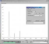
With a 47k resistor across the output, I can adjust the volume control of the BA-3 and see the results in the graph. I can change the frequency that comes out of sound card, and I can see the results in the graph. My problem is that when I adjust P3, NOTHING happens to the graph AT ALL. I know that P3 is actually in the circuit and functioning, because I can measure voltage drop across R3 and R4 and adjust this with P3 quite easily.
Attached is a screen cap of the software. 2nd and 3rd harmonics are there, but I am unable to change the relative magnitude of either. I am using a 25-turn Bourns pot and turning the pot as much as six revolutions either way from the "center" makes no difference in the graph, but does impact voltage drop across R3 and R4.
Any ideas about what I am doing wrong? Wrong software? Wrong technique?
Soundcard Audio Tools and Toys
With a 47k resistor across the output, I can adjust the volume control of the BA-3 and see the results in the graph. I can change the frequency that comes out of sound card, and I can see the results in the graph. My problem is that when I adjust P3, NOTHING happens to the graph AT ALL. I know that P3 is actually in the circuit and functioning, because I can measure voltage drop across R3 and R4 and adjust this with P3 quite easily.
Attached is a screen cap of the software. 2nd and 3rd harmonics are there, but I am unable to change the relative magnitude of either. I am using a 25-turn Bourns pot and turning the pot as much as six revolutions either way from the "center" makes no difference in the graph, but does impact voltage drop across R3 and R4.
Any ideas about what I am doing wrong? Wrong software? Wrong technique?
Attachments
Last edited:
Eric very strange indeed. Sorry to ask an obvious question but are you sure you're seeing the output of the amplifier and not a loop back from the sound card ? The only other thing I can think of is maybe that the load needs to be lowered to say 10k so the distortion products are larger.
Last edited:
I think you are seeing the output of the signal generator straight into the sound card...i.e., the amp is not in the circuit. Try raising and lowering the volume on the amp. Does the graph change? If not, you have the wrong input or something selected in the software. Either that or the sample time is pretty long. Depending on the software it could take minutes to react.
Also, six turns is not a lot. I keep turning until I see action. And your 2nd harmonic is pretty low right now, in fact it's right about where I like it (if that is actually the output of the amp) Also, depending on your soundcard or audio interface you might not need a dummy load resistor. I didn't use one when adjusting mine but I was using a USB audio interface.
Also, six turns is not a lot. I keep turning until I see action. And your 2nd harmonic is pretty low right now, in fact it's right about where I like it (if that is actually the output of the amp) Also, depending on your soundcard or audio interface you might not need a dummy load resistor. I didn't use one when adjusting mine but I was using a USB audio interface.
Last edited:
Pass DIY Addict
Joined 2000
Paid Member
Thanks for the responses, I'll try a few different things tonight. Some additional details:
I am using the BA-3 as a stand-alone preamp.
The BA-3 is indeed working properly, I have been listening to it for a while now and am very pleased with its sound quality. The playback chain is turntable, Pearl II, BA-3, a40, to a set of DIY Tang Band speakers.
The BA-3 is biased a bit higher than spec (~50mA instead of the 45mA target), voltage across R10 and R11 is about 1.15v.
Power supply to the BA-3 is a +/- 27v DIY tracking pre-regulator (Using 3-pin regulators off-piste: part 4), designed to provide 100dB of line noise rejection that uses LEDs as a voltage reference.
The measuring set up is sound card audio out goes into BA-3 input.
Volume control for the BA-3 is Light Dependent Resistor based (matched LDRs from Uriah).
BA-3 output goes to the sound card input.
P3 is a 100R 25-turn pot as specified in the schematic. I have only moved it +/- 6 turns from the middle. I will try all of the way one direction and then the other and also record voltage differences across R3 and R4 when I do so
I am reasonably sure it is connected properly because varying the BA-3 volume control immediately reflects in the amplitudes of the spikes seen on the screen. Same thing happens if I change the output frequency - immediate update on the screen.
I will also try different loads on the output. I used 47k, I'll try increasing and decreasing (and omitting) this and adjusting P3 to the endpoints and let you know what happens.
Pass DIY Addict
Joined 2000
Paid Member
Did some more extensive measurements and found some strange behavior. I think my original confusion with P3 was because the P1 and P2 bias adjustments are so VERY sensitive. P3, by contrast, needs some cranking in order to make small differences.
Anyhow, here is what I found after doing some FFT Spectrum Analysis and looking at input sensitivities, sine/square wave outputs. These results are with a 51k load resistor on the output and the volume level adjusted so a 1kHz sine output from the BA-3 into my sound card registers a -3dB signal level on the computer. The overall noise floor for my sound card setup is at about -100dB:
Left Channel:
I can adjust P3 to get 2nd order dominant (-72dB) with no 3rd order component (-100dB, disappears into noise floor),
I can adjust P3 so that both 2nd and 3rd order disappear into the noise floor (-100dB),
I am unable to produce a 3rd order dominant response at all.
The left channel will accept an input sine wave of up to 5v RMS before the output starts to show distortion at all volume levels.
Right Channel:
I can adjust P3 to get 2nd order dominant (-76dB) with 3rd order at -80dB,
I can adjust P3 to balance 2nd and 3rd order harmonics (both at -80dB),
I can adjust P3 to get 3rd order dominant (-80dB) with no 2nd order at all (-100dB),
The right channel though, will show visible output distortion if the input sine wave exceeds 2.0Vac RMS regardless of the volume setting.
With a 1.5v RMS input sine wave at 1kHz, both channels start to clip at about 15.5v RMS output (BA-3 has a +/-27vDC power supply). Square waves are clear and sharp-cornered at all audio frequencies.
I don't understand what is causing the differences with P3 measurement behaviors and the huge (2x) difference in input sensitivity. My input JFets are matched to within 0.01mV and the larger output transistors are matched to within about 0.05mV. All other component values match the schematic - I double checked all of the resistor and pot values.
Despite the differences in measurement, it sure makes beautiful music!
Perhaps I need to further isolate and study the signal path in my preamp. I am using half of a DCB1 board for input switching and volume control via on-board LDRs and then feeding this to the BA-3 board.
How much distortion you want and how much of each type is up to the listener.
On the Audio Society of Minnesota website they adjusted a ba-3fe for the lowest
distortion with the proper ratio of 2nd and 3rd harmonic distortion. You might
need a sound card that gives you a better noise floor to do that.
http://passlabs.com/articles/audio-distortion-and-feedback
Pass BA-3 Preamplifier - Audio Society of Minnesota
Yes, it sounds like you may have some kind of problem.
You can compare the gain of both Left and right sides
by maxing out your volume and injecting 1 volts rms at the input.
You should get about 10 volts rms on both the outputs assuming
a gain of 10. Most seem to be getting a gain from 10 to 12 from
what I have read.
With your rail voltage I think you should be able to get about 25
volts peak or 50 volts peak to peak. Assuming an amplifier voltage
gain of 10 you should need 2.5 volts peak or 1.77 volts rms to get
this output. This is with both volume pots maxed out.
Pass DIY Addict
Joined 2000
Paid Member
I've been trying to adjust P3 and it's effect on the sound on My BA3-FE. It's proven to be more tedious and time consuming than I ever imagined. I'm barely getting to the point where I can reliably make adjustments, verify the results with test equipment, and then listen for changes.
I'm using the output of a Keithley 2015 and also using it to measure THD. Unfortunately the FFT function on my scope seems useless for what I'm trying to measure, so I'm using my computer and the ARTA program for spectrum analysis.
I'm sure there are differneces in sound after adjustment P3 because my wife asked me if I had played two different versions of the same song. She was upstairs and had no idea I was doing listening tests.
I'm not sure yet what level of input or output to use. I using a 1K sine wave at 1V RMS for input, and using 1V RMS for output of the preamp. Not sure if I should use some output resistance or not. Still learning.
So far I haven't found anything that sounds better than the halfway point on P3
Eric do you have any more test results to report?
Pass DIY Addict
Joined 2000
Paid Member
Kevin: I think part of the problem of not being able to measure differences as expected using FFT software is that my big mosfets are not precisely matched. I picked the best available that I had at the time when I built my BA-3. My J4 and K5: pair measure 2.16v & 2.18 and my J1 and K3 pair measure 2.14v & 2.20v. I've since left the pots so that both channels match in their 2nd and 3rd harmonics characteristics. I'm thinking they are 3rd harmonic dominant right now. Perhaps because of my limited ability to adjust the harmonics, I never was able to discern much of a difference in which harmonic was dominant.
On the Keithley you can set it up to measure just the second harmonic in isolation and then adjust the trimpot for either a minimum 2nd Harmonic value or a dominat 2nd Harmonic with a certain dB value.I've been trying to adjust P3 and it's effect on the sound on My BA3-FE. It's proven to be more tedious and time consuming than I ever imagined. I'm barely getting to the point where I can reliably make adjustments, verify the results with test equipment, and then listen for changes.
I'm using the output of a Keithley 2015 and also using it to measure THD.
Don't know if that helps you, but it is something else you can try.
I'm sure there are differneces in sound after adjustment P3 because my wife asked me if I had played two different versions of the same song. She was upstairs and had no idea I was doing listening tests.
And which setting did she prefer from upstairs?
Probably the OFF setting.
Hahaha
You can always count on the wife to give her honest opinion about your hobby.
No respect.
Haha
- Home
- Amplifiers
- Pass Labs
- Adjusting P3 - a video