The Aleph J jumper does not affect the F6 in the chassis.
If the components and soldering of the boards check out, install one channel only. Then follow 6L6's power up instructions:
F6 Illustrated Build Guide
If you have a Dim Bulb Tester, use it on first power up in case of any shorts. If the DBT test is successful, take it out and proceed with power up.
If the components and soldering of the boards check out, install one channel only. Then follow 6L6's power up instructions:
F6 Illustrated Build Guide
If you have a Dim Bulb Tester, use it on first power up in case of any shorts. If the DBT test is successful, take it out and proceed with power up.

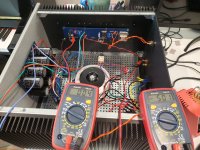
OK. Power supply by istelf measures just over 24v. Put in left channel, looks perfect. I adjusted to 500mv bias, 0 offset. Mosfets started heating up too. Right channel not good. LED lights up, but it's dim, and I measure no voltage across the source resistor. No heat off the mosfets. Below is a pic of the left channel wired up. Guess I will triple check the right channel.
Attachments
First off, thanks everyone for the replies. Right channel makes music, but only if the left channel is totally disconnected. Soon as left channel is even hooked up and turned on, I'm blowing fuses immediately. So I've got the left board out of the amp, and checking it through now. I don't really know what to do besides pull out every component and test. Right channel is on right now as i write this, mosfets at about 100 degrees after 5 minutes. Happy hurricane everyone!
^ One more time, with feeling.... DBT and/or Variac and test one channel at a time until it's confirmed that both are working properly. Blowing fuses that are rated for the full current draw of the amp... might ... mean components have gone poof. If that happened, it may have been avoided by a methodical power-up / early testing process. Personally, I would not power the 'bad channel' again for troubleshooting without one or the other. If you don't have a Variac, and if you don't want to build a DBT, then you could put a lower value 'test' fuse in place before you bias it up all the way. When you know it works, but before you get to full bias, you can replace the fuse with a higher value. It might save some parts.
Not piling on... just a friendly reminder.
I hope you get it up and running. It's a fabulous amplifier.
Not piling on... just a friendly reminder.
I hope you get it up and running. It's a fabulous amplifier.
Keep them separated. i.e. don't short your PSU. Maybe use some tape or other means to cover the exposed ends.
Edited - Wait... I may have read what you said improperly.
If you have wires coming off the PSU, but not connected to the amp boards; cover the ends of the PSU wires.
If you have disconnected the wires from the PSU, but they're still attached to the amp. Don't worry about a thing re: the disconnected amp board or the PSU.
Yep. Thanks again. PSU is fine, wires are taped. I found at least one issue. 1 mosfet I can't get conductance between drain and source after charging the gate for a few seconds. I pulled both mosfets from the board, one tests as it should, the other like I said, I can't get conductance with my multimeter at all. I am sure this was caused by my inexperience and general exuberance. I'll continue to test stuff, but everything else seems alright. I'll buy a couple more mosfets.
I would like to build an F6 using Semisouth SJEP120R063's as I have two "matched" pairs. NP used SJEP120R100's in the article in FIRSTWATT which had 0.1 ohm source resistors. The SJEP120R063's have 0.063 ohms internal resistance from Drain to Source, and the SJEP120r100's have 0.10 ohms internal resistance from Drain to Source. Will I need to change the source resistors in the circuit to 0.137 when using the SJEP120R063's?
Attachments
- Home
- Amplifiers
- Pass Labs
- The diyAudio Firstwatt F6