For the loop breaker, I would go between the center point of the main filter capacitors and earth connection to the chassis close to the IEC inlet.
Bias adjustment.
Hi guys.
I set up a BA3 for an F4 and F5 and I'm having a problem with the adjustment of the bias, a tiny touch on trimmers 1 and 2 in any direction of rotation, there is a huge increase in all values of R10 / 11 and the offset, I am not getting a fine adjustment, the difficulty is greater in one of the channels. The transistors are FQP3P20 / N30 with 1K trimmers. There is something that can change?
Thanks.
P. Dias
change trimpots to multiturns , and decrease them to 470R (500R)
if you can't reach prescribed Iq, increase R6, R7 to 220R or 330R
if you can't reach prescribed Iq, increase R6, R7 to 220R or 330R
to diasell #2002
Hello diasell,
do what ZenMod suggested. Use 25 - turn - trimpots.
The BA-3 FE is well known for this behaviour (especially in the upper bias range).
I think you have +-24 V rails? You can bias it a little lower for the beginning
(perhaps up to 800mV over R10/R11).
I have built 4 of the BA-3 frontends. All behaved very very sensitive to adjustments at Pot 1 / Pot 2 in the upper bias range.
Patience is your friend!!! 🙄
No windblows over the JFets - stop breathing (sorry! - a joke!) 😀
This is not done in 10 minutes....
Have success!
Greets
Dirk
Also, it helps a lot to connect 2.2k resistors from output to ground during bias. It gives the circuit a load and smooths out the adjustment.
Thanks for the quick response.
I use trimpots 25 turns, that's the problem.
It has worked a long time with 80% of the value, previously it had been difficult to fine tune.
Less than 1 degree in the rotation of the trimpot increases the offset by 0.5 v to positive or negative.
Almost with a breath in the trimpot and the value changes.
I will make these changes and hope for the best, however it works, and how it works.
Thank you.
P. Dias
Hello diasell,
do what ZenMod suggested. Use 25 - turn - trimpots.
The BA-3 FE is well known for this behaviour (especially in the upper bias range).
I think you have +-24 V rails? You can bias it a little lower for the beginning
(perhaps up to 800mV over R10/R11).
I have built 4 of the BA-3 frontends. All behaved very very sensitive to adjustments at Pot 1 / Pot 2 in the upper bias range.
Patience is your friend!!! 🙄
No windblows over the JFets - stop breathing (sorry! - a joke!) 😀
This is not done in 10 minutes....
Have success!
Greets
Dirk
If the jfets react so very sensitive to slight air-movement/temperature-changes, why not make a dummy container (the chassis with a cardboard-cover for example, and put a little tube that fits the screwdriver between the pot and the cover?
Just 2c
Bias and setting of P3
Bias -
The procedure for setting bias on the BA-3 FE is almost identical to setting an F5, so this might seem familiar...
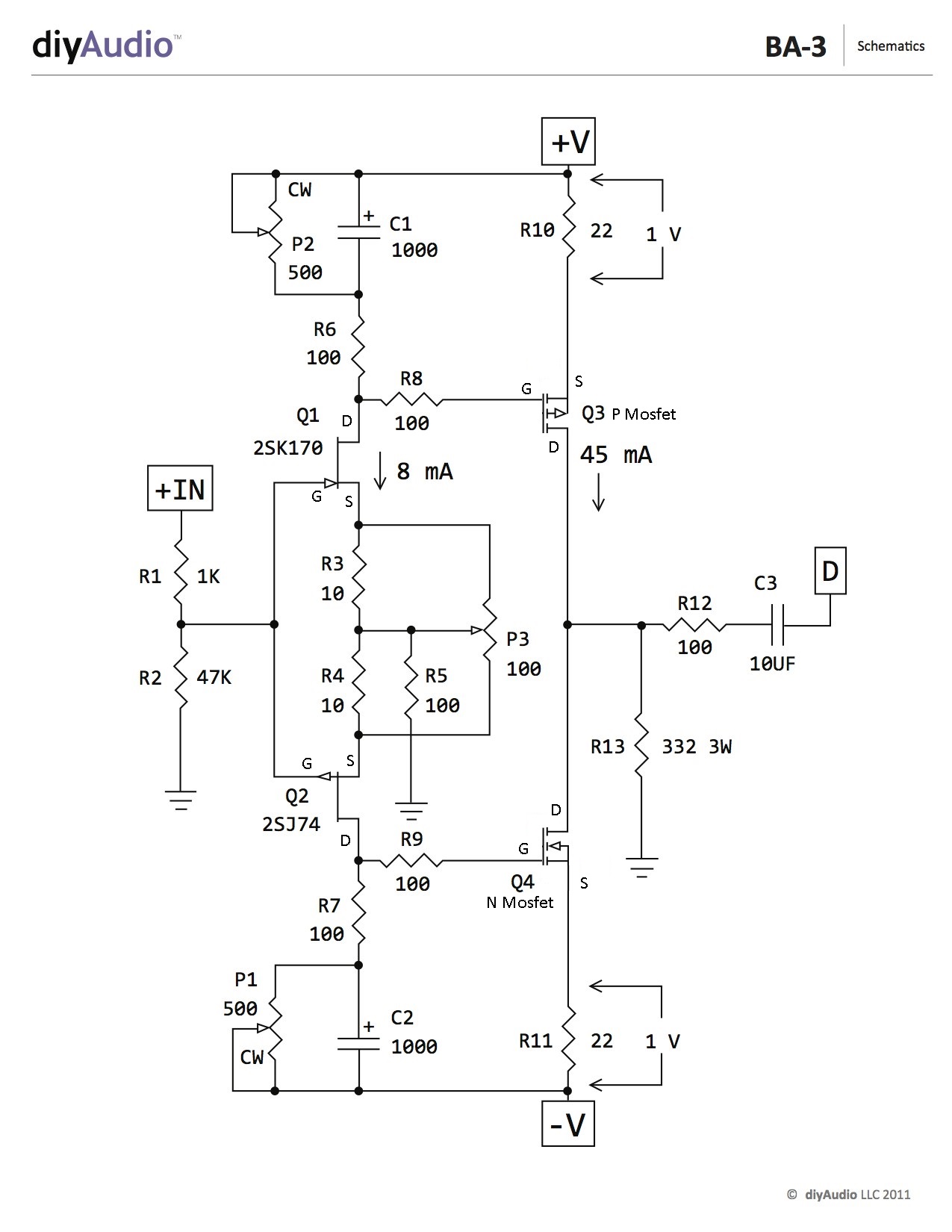
Adjustments (Bias and Offset, set with P1 and P2)
This is easiest with three DMM.
Shorting the input jacks is helpful, although not strictly necessary.
Before power up, dial pots P1 and P2 to 0 ohms . DON'T adjust P3 during bias
Place one voltmeter (Set to DC volts) from R12 to ground - to observe DC offset
Place a voltmeter (Set to DC volts) across R11 another across R10.
For test - slowly dial up Variac ( presuming that you have one , as man with many skills) up to full mains voltage , observing rail voltage at PSU ....... thinking about max cap voltage ( 25V as in FW ? ) , because with 0 Iq PSU is unloaded and voltage is maxed (It’s useful to have another meter for this…) If nothing is smells bad, and the magic smoke is still in the circuit - leave Variac at full mains ;
IF you don’t have a Variac, you must build a lightbulb mains lead. (with a 25W bulb)
What's important - Iq (measured as the voltage across source resistors; the Mosfet bias) must be very low , offset is irrelevant in this moment .
Now turn one pot one turn ( assuming that you have multiturn pots) then turn other pot one turn. Continue, one turn at a time on each pot until something happens.
Observe voltage across resistors and output DC offset.
Proceed one then second pot , again just one turn
Observe Iq and offset
Again one turn + one turn
Now you are probably in range when you can see which pot is pulling offset in right direction - to 0 . It will feel like one of the pots is controlling the bias on both sides, and the other is controlling the DC offset.
It’s best to increase the bias a bit, and then zero the offset. As you zero the offset you will decrease some of the bias, so it will be two steps forward and one step back. That action is normal.
As you increase the bias and zero the offset, remember to always keep the offset near zero. If you run out of turn on the pots, determine your max bias, with zero offset. (It’s useful for troubleshooting)
Proceed iteratively with pots , while you set - say - 75% of desired bias, with zero offset. Remember, full bias is 1V across R10 and R11, with zero offset BEFORE the capacator. If you measure after the cap there should always be no DC.
Now - put lid on box and let it cook for a while - until you get thermal equilibrium on heatsinks
It's best to use wire/clips to leave those voltmeters in place ;
Open the lid , up bias to - say - 90% of desired one ,while maintaining offset
Put lid on , let it cook.
Check again.
If all is OK - move voltmeters for Bias and offset to other channel and repeat procedure.
Use it few days at 90% of desired bias , then check and set to 100%
Remember - temp. equilibrium with lid on is important.
Setting P3 - BEFORE installing and soldering P3 it’s best to adjust the pot so you have equal resistance from pin 1-2 and pin 2-3.
If you didn’t set it, determine how many turns the pot has. Run the pot all the way to one limit (they usually click) and then turn the adjustment the other way for 1/2 of it’s turns. (I.E.,if a 25-turn pot, adjust it 12.5 turns.)
Assuming well matched Jfets the neutral position is going to sound really nice, with 2nd harmonic dominant at most levels. IF you have access to a distortion analyzer, or a high-resolution FFT (or both…) give the amp a 1K test sine wave that outputs 3V measured at the output. Then adjust P3 as necessary for the harmonics you prefer. If you adjust for minimum THD, you will likely have nulled out most of the 2nd harmonic and made it 3rd dominant, which in my opinion makes it very fast and clean, at the expense of soul. YMMV.
Anyway, if you DON’T have a distortion analyzer or similar, take careful notes and turn the pot a few turns (or more) in whatever direction you want and see what it sounds like. It’s a subtle change, but I think you will sense something. You can refer to you notes and see where you like the pot the best. And if you ever get lost, set it back to neutral, (with the power off) just bottom the pot in one direction and set it back to 1/2 it’s travel.
Here we are as you can see...something wrong It seems to me Was done
Attachments


Last edited:
What is your DC offset? (R12 to GND)
The more important question, what is maximum bias you can obtain with zero DC offset?
The more important question, what is maximum bias you can obtain with zero DC offset?
de118 #2008
Hello de118,
nothing is wrong till now! You only have a very large offset between the n- and the p-channel bias.
If you adjust P1 or P2 try to get equal values at your DMMs over the bias resistors (R10/R11). They will not be exactly the same value (in mV) if you try to bring your offset close to zero mV. During adjustments on P1/P2 try to keep offset below 50mV (sometimes I go up to 100mV).
You will need patience! 😉
And you have to measure your offset - check pics below.
I wish you success! and patience! 😀
Greets
Dirk
Attachments


Thank you very much to you dear cubicincher and the ubiquitous 6L6.
I try now and let you know!!
I try now and let you know!!
de118 #2008
Hello de118,
nothing is wrong till now! You only have a very large offset between the n- and the p-channel bias.
If you adjust P1 or P2 try to get equal values at your DMMs over the bias resistors (R10/R11). They will not be exactly the same value (in mV) if you try to bring your offset close to zero mV. During adjustments on P1/P2 try to keep offset below 50mV (sometimes I go up to 100mV).
You will need patience! 😉
And you have to measure your offset - check pics below.
I wish you success! and patience! 😀
Greets
Dirk
Hello de118,
nothing is wrong till now! You only have a very large offset between the n- and the p-channel bias.
If you adjust P1 or P2 try to get equal values at your DMMs over the bias resistors (R10/R11). They will not be exactly the same value (in mV) if you try to bring your offset close to zero mV. During adjustments on P1/P2 try to keep offset below 50mV (sometimes I go up to 100mV).
You will need patience! 😉
And you have to measure your offset - check pics below.
I wish you success! and patience! 😀
Greets
Dirk
Hello all
I need your help to solve the problem of starting my BA-3 pre, I have a Lm317/337 power supply set to 24V to supply the BA-3 pre, when I connected the BA-3 pre for the 1st time, the heatsink of the LM337 (-24v) reached 120ºC in less than 1 min, the LM317 heatsink (+ 24v) was at 40ºC. The voltage dropped to very low values (+ 15v and -10 v) simultaneously, the Mosfet Q4 heatsink of one channel reached 50ºC, the heatsink of the Mosfet Q3 of the same channel reached 36ºC ....
The sinks of the Mosfets on the other channel barely heated up.
All of this was done with a lightbulb mains lead on and the lamp very bright.
Someone can help me?
Do I have a short circuit, or is my power supply defective or am I mistaken in some component and I don't see it?
I removed the BA-3 plate to see if there was any component in the wrong place, but I can't find anything wrong ....
Any hypothesis is welcome,
Thanks
Best regards
Carlos
Attachments
-
 P_20210121_121349.jpg199.2 KB · Views: 451
 -
 P_20210121_121427.jpg192.3 KB · Views: 438
 -
 P_20210121_121557.jpg226 KB · Views: 437
 -
 P_20210121_121716.jpg157.3 KB · Views: 448
 -
 module-alimentation-lineaire-regule-double-lm317-337-tl431-5v-a-37v-15a (1).jpg84.3 KB · Views: 408
 -
 module-alimentation-lineaire-regule-double-lm317-337-tl431-5v-a-37v-15a.jpg136.8 KB · Views: 240
You better test the PSU by itself first. LM317/337 doesn't need a load to operate. Make sure you have the correct voltages out of the reg.
If PSU is good it looks like your mosfets are installed correctly. Are they isolated from the heatsink? Check with a meter. If they are not and they are touching each other that's a bad thing.
I see some areas where solder has not flowed to the top of the PCB. That's not a bad thing in itself but can we see the underside of your PCB too?
Hello Hikari1
The psu seems to be working well, but i will test it, i remembered that i have 24v fans, i will connect them to the psu to see its behavior. The mosfets are isolated from the heatsinks and these are spaced apart (although it doesn't look like it).
Thank you for your help.
greetings.
Carlos
The psu seems to be working well, but i will test it, i remembered that i have 24v fans, i will connect them to the psu to see its behavior. The mosfets are isolated from the heatsinks and these are spaced apart (although it doesn't look like it).
Thank you for your help.
greetings.
Carlos
Attachments

@ diplomata
Is your power supply and BA-3 board in the same chassis or connected by umbilical from separate chassis?
Is your power supply and BA-3 board in the same chassis or connected by umbilical from separate chassis?
Hello Hikari1
The psu seems to be working well, but i will test it, i remembered that i have 24v fans, i will connect them to the psu to see its behavior. The mosfets are isolated from the heatsinks and these are spaced apart (although it doesn't look like it).
Thank you for your help.
greetings.
Carlos
Well, I would reflow all the solder joints...just to make sure. Some of the solder joints appear like they may not have enough solder although it’s hard to be sure in the pic. make sure mosfets are installed correctly...although they appear they are. Jfets are from a reliable source?
I would check the trim pots with a meter to make sure they are still operational. That is a lot of current flowing through those pots.
Did you start up the amp with bias too high? What was the initial bias like when you started the amp?
I had a lot of problems with bogus ebay 2SJ313 and 2SK2013 parts.
The first time I turned it on I had resistors smoking.
I bought from local dealers thinking they would have checked out their product
- but no. Had to return several sets.
I got some from prakit on this forum and they worked perfectly.
Thanks prakit!
Awesome preamp by the way!
The first time I turned it on I had resistors smoking.
I bought from local dealers thinking they would have checked out their product
- but no. Had to return several sets.
I got some from prakit on this forum and they worked perfectly.
Thanks prakit!
Awesome preamp by the way!
- Home
- Amplifiers
- Pass Labs
- The BA-3 as preamp build guide