Hi,
i have just bought some nice pcbs to try to build the single ended Bride of Zen
I read something about the relatively high gate capacitance of the recommended mosfet, IRF 610 and 510.
I have two kind questions:
1) which is the best choice of the two ? are they perfectly equivalent ?
2) is this gate capacitance really a problem ?
I had some direct experience of the project.
I just remember that i was amazed by the differences using different power supplies, with a very nice sound coming from a regulated one.
My feeling is that with a very low noise PS the sound will be very very good.
Still i am concerned about the gate capacitance impacting maybe the high freq response
By the way my ears go up to only 15K or so i think ...
Thanks a lot and kind regards, gino
Build two versions.
One as "standard" and one with the 510 cascoded.
Compare and then modify the one that measures/sounds worse.
Hi and thanks a lot for the kind reply.
Sorry but i am quite ignorant ... what means "cascode" ?
I would stick with the original schematic
But in the article both parts 510 and 610 are recommended
Speaking of sound, as the article very well explain, the quality of the PS is decisive.
I have great expectations.
Thanks and regards, gino
use any of them
post schm and I'll show you how to make cascoded one
in a meantime , read this http://www.firstwatt.com/pdf/art_cas_amp.pdf
and all other articles at FIRST WATT ARTICLES
post schm and I'll show you how to make cascoded one
in a meantime , read this http://www.firstwatt.com/pdf/art_cas_amp.pdf
and all other articles at FIRST WATT ARTICLES
use any of them
Hello, Thank you very much indeed ! 1st problem solved !
post schm and I'll show you how to make cascoded one
i am not sure what you mean ... the schematic is the one available in the net here below. I hope that the pcbs are built accordingly.
in a meantime , read this http://www.firstwatt.com/pdf/art_cas_amp.pdf
and all other articles at FIRST WATT ARTICLES
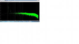
Wow ! very impressive distortion spectrum
I am exclusively interested in line stages for now.
And do you think that is possible to mod the original schema to cascode ?
It looks a little complicated to me ... but the trace on the scope is very impressive ... completely clean !

Thanks and regards, gino
Attachments
Try an IRF614 - lower gate capacitance.
Thanks a lot for the valuable reply
I am modifying the schema a little, moving the pot at the input
I would like to use a 10K-20K attenuator ... or a nice potentiometer
The gain is a little high for a line stage.
Thanks again.
Regards, gino
Thanks a lot for the very interesting advice.
This mod makes things more complicated ... and you say that there is a big improvement in terms of distortion ?
And will these improvements be evident even in a low level system ?
The rest of the chain is nothing special.
I am worried because one thing is to solder parts on a pcb another one is to start from a schema ...
Anyway i will think about it.
Interesting this cascode arrangement. Very much indeed.
Thanks again and kind regards, gino
Last edited:
Hi and sorry to bother you but i have another question.
I have received some pcb for the BOZ and i decided to go with the original design ... but with possibly some changes.
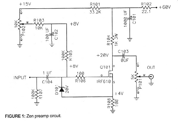
Looking at the original schema here below, if i understand correctly the gain is 10 (i.e. R104/R108) and the out impedance 1kohm (i.e. R104)
is it possible to decrease the gain at around 2 and the output impedance at around 500 ohm ?
Which components i should change ?
My idea:
R104 = 470 ohm
R108 = 220 ohm
Vsupply = 48V
This shoud give gain around 2 and out impedance = 470 ohm. Am i right ?
Could i keep all the rest unchanged ?
Thanks a lot. Regards, gino
I have received some pcb for the BOZ and i decided to go with the original design ... but with possibly some changes.
Looking at the original schema here below, if i understand correctly the gain is 10 (i.e. R104/R108) and the out impedance 1kohm (i.e. R104)
is it possible to decrease the gain at around 2 and the output impedance at around 500 ohm ?
Which components i should change ?
My idea:
R104 = 470 ohm
R108 = 220 ohm
Vsupply = 48V
This shoud give gain around 2 and out impedance = 470 ohm. Am i right ?
Could i keep all the rest unchanged ?
Thanks a lot. Regards, gino
Last edited:
when you change the resistor values you also change the bias current.
you will need to re-set the bias to obtain ~16Vdc at the output, based on Vcc=48Vdc.
That will push twice the current through the 610 and make it dissipate nearly twice as many watts.
The source resistor may require to be changed to suit the new dissipations and that would change the gain from your desired 2times.
Hi and thanks for the reply
I honestly do not understand why line stages must have such a high gain
CD and phono preamps put out around 1-2V i think
In many cases a volume pot and a buffer is what is needed to drive properly a normal power amp
Anyway .... i wonder if i could replace all the bias circuit with just two resistors in front of the 610 as with bjts (i think it is called a voltage divider ?)

Is the 4 V drop across the 610 a fix value ?
I have to check this evening if there is the model of this mosfet in LTSpice ...
I think i have found something ...
Vishay - MOSFETs - IRF610, SiHF610 - Power MOSFET
Now the problem would be to load the model in LTSpice ...
Thanks again, gino
I honestly do not understand why line stages must have such a high gain
CD and phono preamps put out around 1-2V i think
In many cases a volume pot and a buffer is what is needed to drive properly a normal power amp
Anyway .... i wonder if i could replace all the bias circuit with just two resistors in front of the 610 as with bjts (i think it is called a voltage divider ?)
Is the 4 V drop across the 610 a fix value ?
I have to check this evening if there is the model of this mosfet in LTSpice ...
I think i have found something ...
Vishay - MOSFETs - IRF610, SiHF610 - Power MOSFET
Now the problem would be to load the model in LTSpice ...
Thanks again, gino
Last edited:
About your statement that many Cd's and phono preamps have all the voltage output needed Nelson made much the same statement so gave us the B1 buffer circuit.
You may want to look at that article if you haven't .
Hi and thanks and actually i have looked at that project
But i have already pcbs for this BOZ and i prefer this project.
I know that it can sound very good indeed.
I was just thinking to change some values and simplify it even more
I understand that for a tube a voltage divider is just enough to set the bias So i wonder if the same can be done for the mosfet
Just two resistors in front of the 610 instead of all the circuit ... i think this is due to filter some noise from the PS maybe ?
Thanks a lot, gino
P.S. i forgot to say pot at the input ... not at the output
Last edited:
About your statement that many Cd's and phono preamps have all the voltage output needed Nelson made much the same statement so gave us the B1 buffer circuit.
You may want to look at that article if you haven't
Hi and so i am right to ask why the gain in the BOZ is so high ... but i understand i am the only one feeling the problem
Maybe it has been designed with low gain power amps in mind ?
Thanks again, gino
the output impedance of 1k is high.
OK it is less than the maximum of a 10k pot, but it is high.
It might be better to put the vol pot after your BoZ and add a buffer after the vol pot.
Personally i would prefer to have a pot at the input and a amp stage after, as usual without input buffers
I think that changing Vsupply and some resistors value both out impedance and gain can be decreased
Moreover i have seen projects on the web, less refined i suppose, where the bias for the mosfet is set with a simple voltage divider
So 4 resistors, one mosftet, two caps should make a stage
This evening i will see if there is the 610 model in LTSpice
On the Vishay site there is but i have problem in importing it in the program
I usually make a mess with this sw ...
Kind regards, gino
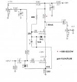
Hi and thanks i understand. I think that a buffer is needed after the pot to drive properly the cable and the power amp that follow.
Instead i was thinking to something really basic like the schema attached
From the fft it has only some 2nd order distortion (nice) and minimal 3rd order
I understand that one thing is the simulation another one the actual performance of a prototype ... but this is what i have in mind
With a pot at the input
Maybe it could "sound" musical
Kind regards, gino
P.S. sorry i cannot upload the fft ...
Attachments
Last edited:
- Status
- This old topic is closed. If you want to reopen this topic, contact a moderator using the "Report Post" button.
- Home
- Amplifiers
- Pass Labs
- Bride of Zen - mosfet gate capacitance