I recently finished my Aleph mono-blocks and am now considering my next amplifier project. I built and anodized a large stereo amplifier chassis at the same time I was building my Aleph mono's and it is completed and just sitting there taunting me to fill it with something. The stereo chassis I built housed an Aleph 5 for a short period and with non-anodized sinks and +/- 35.5V rails when loaded it was holding about 28C above ambient. So I assume with the newly black anodized sinks I should be able to build an amplifier that can safely dissipate ~300W.
Now I would like to build a push-pull Class A Pass amp, but I would like it to be a little different.
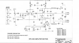
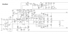
I have had a set of Adcom's old early 90's (Pass designed) amplifiers in my car for a few years now and I have enjoyed them immensely. This has me wondering how one would sound if beefed up and built for home duty. Looking over many of the schematics of the period it appears that the 4302 was a variant of the Pass designed Adcom 5800/5802 amplifiers from the 90's, only with an SMPS power supply for the car. I have a spare Adcom 4302 (schematic attached) that is fully functional and I was considering using it as a predriver with a beefier output stage. I would of course not utilize the SMPS power supply and would just build my own.
Here is what I was thinking about doing for this hybrid car/home amplifier. I have a 1000VA 25V X 2 transformer that I would use as the basis for the nonregulated DC rails. This is the same transformer that gave me the +/- 35.5 VDC rails in my early Aleph 5 build. I would buy a smaller 32vac transformer for the regulated rails to give me +/- 42 vdc for the front end. I would utilize the entire predriver section on the 4302 car amp and mount a separate output stage in my new stereo chassis. The original output stage in the amplifier would be disconnected and not utilized along with the SMPS.
For the new output stage I am wanting to use three IRFP140/IRFP9140's per channel (6 total). The reason for the odd number of outputs is because my chassis is predrilled for the Aleph 5's six output mosfet's per channel. If I stick to that number it will make my life a lot easier. I plan to bias these up to 4A per channel or about 25 watts per output device. This would also keep me below my 300W total dissipation for my chassis.
I think this would make a decent little push-pull amplifier with 128WPC peak Class A, or about 65WPC RMS into my 8 ohm Vandersteen 2Ci's.
So I am wondering what you guys think of this plan? Any and all ideas are welcomed. Any shortfalls or oversights in my plans?
Now I would like to build a push-pull Class A Pass amp, but I would like it to be a little different.
I have had a set of Adcom's old early 90's (Pass designed) amplifiers in my car for a few years now and I have enjoyed them immensely. This has me wondering how one would sound if beefed up and built for home duty. Looking over many of the schematics of the period it appears that the 4302 was a variant of the Pass designed Adcom 5800/5802 amplifiers from the 90's, only with an SMPS power supply for the car. I have a spare Adcom 4302 (schematic attached) that is fully functional and I was considering using it as a predriver with a beefier output stage. I would of course not utilize the SMPS power supply and would just build my own.
Here is what I was thinking about doing for this hybrid car/home amplifier. I have a 1000VA 25V X 2 transformer that I would use as the basis for the nonregulated DC rails. This is the same transformer that gave me the +/- 35.5 VDC rails in my early Aleph 5 build. I would buy a smaller 32vac transformer for the regulated rails to give me +/- 42 vdc for the front end. I would utilize the entire predriver section on the 4302 car amp and mount a separate output stage in my new stereo chassis. The original output stage in the amplifier would be disconnected and not utilized along with the SMPS.
For the new output stage I am wanting to use three IRFP140/IRFP9140's per channel (6 total). The reason for the odd number of outputs is because my chassis is predrilled for the Aleph 5's six output mosfet's per channel. If I stick to that number it will make my life a lot easier. I plan to bias these up to 4A per channel or about 25 watts per output device. This would also keep me below my 300W total dissipation for my chassis.
I think this would make a decent little push-pull amplifier with 128WPC peak Class A, or about 65WPC RMS into my 8 ohm Vandersteen 2Ci's.
So I am wondering what you guys think of this plan? Any and all ideas are welcomed. Any shortfalls or oversights in my plans?
Attachments
The constraints of supply and such lead me to suggest that if you can supply
the front end with another 10 volts of supply (at 100 mA or so then you can
really maximize the output, as here you are somewhat limited by the voltage
swing of the second gain stage, which loses a few volts by virtue of the
swing of the front end itself, but also another 4-5 volts by the bias circuits.
In the "home version" we didn't have to care too much (the reason being that
there is one payback - lower output capacitance), but you will appreciate
that you can get another maybe nine volts peak, enough to increase the
output 33% or so, and lowering the distortion of the front end on top of that.
On second viewing, I see that this has that.
Nevermind.
On second viewing, I see that this has that.
Nevermind.
Mr. Pass,
I was only thinking of +6 - 7V of overhead on the regulated front end. Reading your comments, I'll push it up to at least +10V over the non-regulated rails.
As the saying goes, so many projects so little time!
A big thank you for all of the great projects Mr. Pass!
Kevin
Mr. Pass,
I was only thinking of +6 - 7V of overhead on the regulated front end. Reading your comments, I'll push it up to at least +10V over the non-regulated rails.
Looking again, that cascode and the reference voltage chew up a lot of swing.
Make it 12 volts.
Looking again, that cascode and the reference voltage chew up a lot of swing.
Make it 12 volts.
Antek has a 25VA 40V transformer which is probably overkill, but overkill is something we all strive for at DIYAUDIO.
For the price I'll get two of them and make separate L/R regulated supplies with the single 1000VA toroid for the non-regulated. This will be just like the 5800/5802 home amps power supplies.
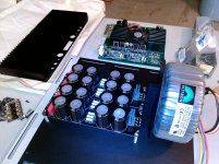
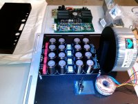
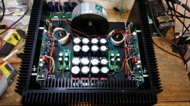
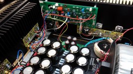
I began assembling the new hybrid Pass amplifier tonight. My Adcom donor automotive amp is in the background. I placed a 30VA toroid and proto board in one of the pictures. I will probably position the new 25VA toroids I ordered from Antek in this manner on either side of the larger low voltage supply.
I am a little light on capacitance in my low voltage supply. The 16 caps on the supply boards are 8,200uF/50V Nichicon KG's. I had these sitting on the shelf for a few years and for some reason I thought they were 12k uF's. I might just try it out with the 131K uF total that is there now and see how bad the hum is then add capacitance if needed.
Now I need to order some output mosfets and get started matching.....
Attachments
I have decided to go with the IRFP240/IRFP9140 outputs. I have bunch of matched 240's left over from my Aleph so I will only need to buy 9140's and there is a lot of info on the 9140/240 combo being a better pairing.
An interesting observation,
None of the Adcom car amps used source degeneration resistors on the output stage. I did some searching online and checking out pictures of the internals on the various Adcom models. The provision is there on the amplifier boards and is shown in the schematic, but a jumper is installed in the actual production amps. I understand the jumper install for the single output device versions, but not for the paralleled output versions, i.e. 4402, 4404 & 4702. I cannot see Adcom having matched those parallel output mosfets so well that a small amount of source resistance would not have been preferable over the jumper.
Even though I match my outputs tightly at 10 mV I was planning to use 0.22 or 0.33 ohm source degen resistors in my hybrid, any thoughts on this?
.....
Even though I match my outputs tightly at 10 mV I was planning to use 0.22 or 0.33 ohm source degen resistors in my hybrid, any thoughts on this?
yup
take a look on F4 output stage , same as BA3 .
I've been slowing piecing together how I want to proceed with this project. After a bunch more researching it turns out the Adcom 5XXX series of home amps is essentially the same amp design as the old Adcom auto amps, no SMPS of course. I was having some reservations of dismantling the working 4302 Adcom auto amp that I had for this project, there do not seem to be a lot of them out there. I ended up settling on an Adcom 5400 which has the 6 output mosfets per channel that I desired. There are so many of the Adcom home amps out there that I don't mind tearing one of them apart.
I picked a broken one up off the 'bay for a bargain basement price. It turns out the only issue with it was the bias pot was trashed. I replaced the pot and both channels biased right up and sounded great. Then as a test I put the stock transformer primaries in series, dropping the DC rails in half and biased it up to about 20 WPC RMS Class A with a room fan blowing on it. The rails loaded were about 30 VDC like this. The heatsinks stayed at an acceptable temp and it sounded real nice. No anomalies seen on the scope when driving my 8 ohm resistor load. So I'm ready to dismantle it and put it into my monster chassis and REALLY crank up the bias.
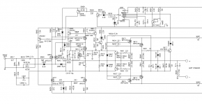
My chassis is machined for both XLR & RCA in's so I want to wire these boards up for the XLR's. The Adcom 5800 amp is an identical design so I copied the XLR in's from this amp and put them into a modded 5400 schematic that I have attached. If some of you guys could look at it and give me a thumbs up or down and suggestions for improvement that would be great. I also attached a 5300 schematic for comparison purposes, this is the most comparable schematic to what I am working with. It turns out there are several versions of these Adcom amps out there and mine is the most recent so it has all of the bells and whistles, some of which I plan to do away with. I plan to eliminate the current triggering circuit that was hanging off the last output mosfet pair in the attached 5300 schm triggering the 555. I deleted this in my modded circuit I attached. I will however leave the 555 time delayed thermal trigger intact.
I picked a broken one up off the 'bay for a bargain basement price. It turns out the only issue with it was the bias pot was trashed. I replaced the pot and both channels biased right up and sounded great. Then as a test I put the stock transformer primaries in series, dropping the DC rails in half and biased it up to about 20 WPC RMS Class A with a room fan blowing on it. The rails loaded were about 30 VDC like this. The heatsinks stayed at an acceptable temp and it sounded real nice. No anomalies seen on the scope when driving my 8 ohm resistor load. So I'm ready to dismantle it and put it into my monster chassis and REALLY crank up the bias.
My chassis is machined for both XLR & RCA in's so I want to wire these boards up for the XLR's. The Adcom 5800 amp is an identical design so I copied the XLR in's from this amp and put them into a modded 5400 schematic that I have attached. If some of you guys could look at it and give me a thumbs up or down and suggestions for improvement that would be great. I also attached a 5300 schematic for comparison purposes, this is the most comparable schematic to what I am working with. It turns out there are several versions of these Adcom amps out there and mine is the most recent so it has all of the bells and whistles, some of which I plan to do away with. I plan to eliminate the current triggering circuit that was hanging off the last output mosfet pair in the attached 5300 schm triggering the 555. I deleted this in my modded circuit I attached. I will however leave the 555 time delayed thermal trigger intact.
Attachments
Hey now, keep your pants on. There's a yummy class A amp bottled away like a magic genie inside every one of those Adcom Mosfet amps if you rub it the right way.There are so many of the Adcom home amps out there that I don't mind tearing one of them apart.
Hey now, keep your pants on. There's a yummy class A amp bottled away like a magic genie inside every one of those Adcom Mosfet amps if you rub it the right way.
Well I was hoping for the genie, but I'll take the Class A Pass amp as a consolation prize.
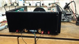
Its been a while, but I finally found some time over the past several weeks to get this amplifier together. I biased it up to a little over 600ma per output device (about 50W Class A) and it sounds nice on my little bookshelf speakers. The heatsinks were running at 48C and are of course going to be my limiting factor for more bias. Amazingly enough it powered up perfectly the first time, no problems at all. I'm at +/-36 VDC for the output stage rails and +/- 54 VDC for the input stage rails. The 36V ended up being about 2 - 3V higher than I had hoped for when loaded and that is even with a highish .2 ohm R in my CRC.
The only issue I have is that for some reason my irfp240's are not matched that well. The IRFP9140 triples for each channel are all within a few milliamps of each other, but I ended up with a 40ma difference for one each of irfp240 triples on each channel. I'm not sure how that happened, I spent a lot of time trying to make sure they were matched perfectly. I'm guessing the rather low voltage I used [13V/500ma] used for Vgs matching wasn't optimal. Anyway, I'll have to dig some more 240's out and see about getting a closer match.
I included a few pictures. I still need to machine a plate to mount my IEC AC jack and then I can begin finishing it up.
Attachments
- Status
- This old topic is closed. If you want to reopen this topic, contact a moderator using the "Report Post" button.
- Home
- Amplifiers
- Pass Labs
- Pass hybrid Car/Home Class A amplifier project