Hi Folks,
I just finished building my F5 but have yet to get it working properly.
1) I'm getting +/-26V for V+ and V- off of the Universal PSU v3.0. I see that Papa has specified +/-23V. I'd like to get the supply as close to +/-23V as possible to match the First Watt specs. What should I check as the problem?
2) I also tried to adjust the bias on both channels but I'm not able to get past .57V on the right channel and .47V on the left channel. Offset was steady at 0V. I'm thinking I may need to check my MOSFET Vgs and maybe change R7/R8 (formerly R11/R12 on v2.0?) to higher values? I see some people have gone up to 3.3k to fix similar bias issues on the F5 v2.0 PCBs.
I'll have to check the voltage at R7/R8 (formerly R11/R12 on v2.0?) and see if I get .6V. I'll also have to check R5/R6 (formerly R3/R4 on v2.0?) and see if I get 42V.
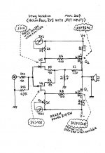
I used Papa's F5 schematic on page 2 of his F5 Turbo article to build these F5 v3.0 boards. FYI, I set P3 to dead center by checking resistance before installing and I'll adjust it once I get everything else sorted.
Thanks for your help.
I just finished building my F5 but have yet to get it working properly.
1) I'm getting +/-26V for V+ and V- off of the Universal PSU v3.0. I see that Papa has specified +/-23V. I'd like to get the supply as close to +/-23V as possible to match the First Watt specs. What should I check as the problem?
2) I also tried to adjust the bias on both channels but I'm not able to get past .57V on the right channel and .47V on the left channel. Offset was steady at 0V. I'm thinking I may need to check my MOSFET Vgs and maybe change R7/R8 (formerly R11/R12 on v2.0?) to higher values? I see some people have gone up to 3.3k to fix similar bias issues on the F5 v2.0 PCBs.
I'll have to check the voltage at R7/R8 (formerly R11/R12 on v2.0?) and see if I get .6V. I'll also have to check R5/R6 (formerly R3/R4 on v2.0?) and see if I get 42V.
I used Papa's F5 schematic on page 2 of his F5 Turbo article to build these F5 v3.0 boards. FYI, I set P3 to dead center by checking resistance before installing and I'll adjust it once I get everything else sorted.
Thanks for your help.
Feds,
measure the voltage drop across each of the jFET source resistors.
From that you can estimate the jFET current.
Measure the total resistance across the mosFET Gate to Source.
Multiply the jFET current times the GS resistance to estimate the expected maximum Vgs.
Measure the mosFET Vgs to see if that is what you are getting.
1) I'm getting +/-26V for V+ and V- off of the Universal PSU v3.0. I see that Papa has specified +/-23V. I'd like to get the supply as close to +/-23V as possible to match the First Watt specs. What should I check as the problem?
If you are measuring the PSU with no load, there is no problem, it will reduce with load.
Anyway, unless you have 25V caps in the PSU, it genuinely doesn't matter.
That's awfully close striaght away (and kudos for determining how much bias you can get with zero offset). Anyway, you should only need to increase the parallel resistors across the bias pots by 2 or 3K to give enough resistance to set the bias properly. Heck - I have an F5 with V grade jfets and it took 10K in parallel with the pot to get things operating happily. Sounds and measures great, BTW.2) I also tried to adjust the bias on both channels but I'm not able to get past .57V on the right channel and .47V on the left channel. Offset was steady at 0V.
A good place to start. You can mess with the pot once everything else is happy by counting turns in one direction or another. Take notes every time you adjust P3. And also, if you ever get lost, just bottom the pot in either direction and turn it back 12.5 turns - that will be close enough to the center to be no matter.I set P3 to dead center by checking resistance before installing and I'll adjust it once I get everything else sorted.
May we see some photos of your build?

Hi Folks, thank you for the advice. I won't be able to try any of these suggestions out until Tuesday.
More info I forgot to provide on the build:
Used lsk170 and lsj74 B grade matched at 9 right and 9.8 left
Used ztx550 and ztx560 didn't bother matching since I read that boarding would compensate.
Used irfp240 and itfp940 didn't bother matching. Thought boasting would compensate.
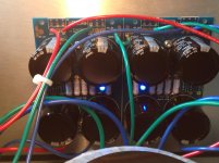
I'm not sure if the polarity of the LEDs changed from v2.0 to v3.0 but I installed my blue LEDs long lead as positive into round pad and it didn't work for me. Flipped it to match the diode symbol and it worked.
Pictures to follow on Tuesday. Sorry about that, I knew better than to post without =D
More info I forgot to provide on the build:
Used lsk170 and lsj74 B grade matched at 9 right and 9.8 left
Used ztx550 and ztx560 didn't bother matching since I read that boarding would compensate.
Used irfp240 and itfp940 didn't bother matching. Thought boasting would compensate.
I'm not sure if the polarity of the LEDs changed from v2.0 to v3.0 but I installed my blue LEDs long lead as positive into round pad and it didn't work for me. Flipped it to match the diode symbol and it worked.
Pictures to follow on Tuesday. Sorry about that, I knew better than to post without =D
FYI, I used the method described in the following links to match my JFETs. 6L6 and Tinitus describe the method and provide links.
Posts #11244 #11245 in the F5 Amp thread.
http://www.diyaudio.com/forums/pass-labs/121228-f5-power-amplifier-1125.html
Transistor matching
I'll try what AudioSan, Andrew and 6L6 have suggested and will get back with more info.
Thanks guys.
Posts #11244 #11245 in the F5 Amp thread.
http://www.diyaudio.com/forums/pass-labs/121228-f5-power-amplifier-1125.html
Transistor matching
I'll try what AudioSan, Andrew and 6L6 have suggested and will get back with more info.
Thanks guys.
I just think that 9.0ma and 9.8ma are not that close a match. Spencer's Jfets are within 0.2ma of each other at 10vdc. I would be interested in learning how many ma's are flowing thru the Jfets as suggested earlier. I suppose pot P3 could also be used to fine tune this.
nash
nash
use what you have , in 20-25% ballpark
our dear Baobabwana made his first F5 lookalike with J309 and 2SJ108 years ago ...... you'll get much better match ....... due to balancing nature of circuit
our dear Baobabwana made his first F5 lookalike with J309 and 2SJ108 years ago ...... you'll get much better match ....... due to balancing nature of circuit
Attachments
Last edited:
I just think that 9.0ma and 9.8ma are not that close a match. Spencer's Jfets are within 0.2ma of each other at 10vdc. I would be interested in learning how many ma's are flowing thru the Jfets as suggested earlier. I suppose pot P3 could also be used to fine tune this.
nash
So all 4 JFETs across both channels need to be within .2ma of each other?
I matched the lsk170/lsj74 pair at 9.0ma for the right channel.
I matched the lsk170/lsj74 pair at 9.8ma for the left channel.
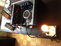
One more thing I forgot to mention. I left my dim bulb tester in place as I set the bias. When bias was at zero the bulb was off but as I increased the bias the bulb started to light up until it was bright. I am using a 75watt bulb. At first it worried me to see the bulb light up but then I figured maybe it's lighted because it's operating in class a. Am I wrong to think this?
Photos
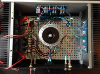
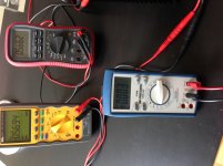
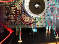
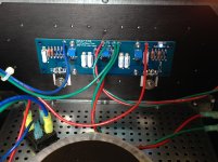
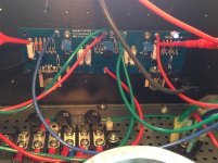
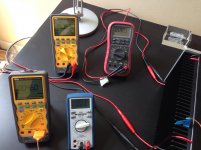
Here are some photos.
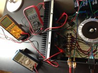
Photos show the measurements for the Right Channel:
Blue DMM is the DC offset
Red DMM is P1 R7
Yellow DMM is P2 R8
The bulb is a 75 watt and it only lights up when the bias is dialed up. I'll take it out of the loop as ZenMod suggests.
Also, the temperature of the heatsink is barely warm at .57V bias. Is this normal? I guess I could check the spec sheets to see how temperature ramps up as bias is increased?
Another little thing, the LEDs on the channels are dim. I used a 33k resistor. I'll probably swap it out for a lower resistor like I used on the PSU to get a slightly brighter LED.
Here are some photos.
Photos show the measurements for the Right Channel:
Blue DMM is the DC offset
Red DMM is P1 R7
Yellow DMM is P2 R8
The bulb is a 75 watt and it only lights up when the bias is dialed up. I'll take it out of the loop as ZenMod suggests.
Also, the temperature of the heatsink is barely warm at .57V bias. Is this normal? I guess I could check the spec sheets to see how temperature ramps up as bias is increased?
Another little thing, the LEDs on the channels are dim. I used a 33k resistor. I'll probably swap it out for a lower resistor like I used on the PSU to get a slightly brighter LED.
Attachments
turn the bias adjusters back down to zero.
Power Off.
remove bulb tester.
Power On.
Start setting output bias in stages and wait till each pair of changes has time to heat the sinks to near final temperature.
When you reach 90% of the bias you want wait half an hour, while everything heats up.
Adjust towards the final 100% and attach the lid during each "wait" period.
Check offset periodically while the lid is on.
When you are satisfied that the amp temperature is stable, monitor offset and bias over at least 24hrs BEFORE attaching a speaker.
Not a believer in twisted pairs !
WOW! AndrewT and ZenMod were right about taking the dim bulb tester out of the loop. I use it as my safety net (large fuse) so I don't damage anything but I didn't realize it would affect measurements. I was afraid to take it out of the loop, thanks for the advice.
I reduced the bias down to zero and took the dim bulb tester out of the loop. I powered it back up and I immediately noticed much better bias adjustment (the voltage adjustment increases in larger increments without the DBT in place). At the moment I have it set to .4V to let it warm up a bit. It reached .4V with much fewer turns. I also noticed the heatsinks are now starting to warm up. I'm only working on the right channel for now. I'll set the left channel once I have the right channel sorted.
I'll keep everyone posted on the progress.
Yeah, sorry about that. I'm sure I've read it before but I guess I was so worried about frying something that I didn't stop to think.
Update:
It's currently sitting at 38 degs C (I don't have an infrared thermometer so I taped a DMM thermo probe to the outside of the heatsink where the MOSFET is mounted.)
.44V P1 and P2
0V DC offset
Update:
It's currently sitting at 38 degs C (I don't have an infrared thermometer so I taped a DMM thermo probe to the outside of the heatsink where the MOSFET is mounted.)
.44V P1 and P2
0V DC offset
- Status
- This old topic is closed. If you want to reopen this topic, contact a moderator using the "Report Post" button.
- Home
- Amplifiers
- Pass Labs
- F5 v3.0 PSU and Bias Help Needed