Your concern over different dissipations is a non issue.I'm not trying to match Vgs, I'm aware that they are very different. I simply want to make sure that the amp is properly biased. Sometimes you see amps with a output device heating considerably more than the other..this is what I'm trying to avoid. Maybe this can only happen with a different amp topology.
What would happen if R3 and R5 on the input BJT were very different, ex 1K and 1K5 ?
Thanks,
Eric
Keeping in mind that there is no gate current (except for the tiny amount required to charge and discharge the gate capacitance) the device dissipation is Vds * Id
When the Vgs on the +ve and -ve sides are adjusted to give zero output offset, then you know that the Id are the same. What flows down through the Pch must carry on and flow down through the Nch. (again except for the tiny currents that flow in and out of the NFB resistors).
All you need for equal dissipation is for the Vds to be the same. The supply rails and the source resistors are the same, so Vds is equal.
You have equal dissipations.
Eric, there's nothing to fine-tune there:
Low Z feedback loop enforces 12V at the output (small variations are not important because we use the coupling cap anyway) and the S-D channels of output MOSFETs are in serial connection so the same current will flow through them. But since they are not matched, they'll have the different Vgs to provide the same Id. That means that currents through Q1,Q2 won't be the same.
How is that possible when R3=R5 and R4=R6 ?
It works because DC currents won't be the same through both feedback branches in order to provide the initial condition (12V at the output, before the coupling caps). So the DC currents through Q1 and Q2 won't be the same, DC currents through R9,R10 won't be the same, Vgs for both MOSFETs won't be the same, but the gain of input stage BJTs will be the same, the current through MOSFETs will be the same and the output will stand firmly at the half of the PS voltage and that are important things.
So please don't fix what ain't broken...")
If you insist on measuring the Id, it's much less intrusive if you put 0R1 in the drain circuit (no significant influence on Vgs) or in the PS line. Currents in the Drain and Source circuit have to be the same since you got no Gate current (it's not the same for BJTs where emitter current branches on base and collector current)
Low Z feedback loop enforces 12V at the output (small variations are not important because we use the coupling cap anyway) and the S-D channels of output MOSFETs are in serial connection so the same current will flow through them. But since they are not matched, they'll have the different Vgs to provide the same Id. That means that currents through Q1,Q2 won't be the same.
How is that possible when R3=R5 and R4=R6 ?
It works because DC currents won't be the same through both feedback branches in order to provide the initial condition (12V at the output, before the coupling caps). So the DC currents through Q1 and Q2 won't be the same, DC currents through R9,R10 won't be the same, Vgs for both MOSFETs won't be the same, but the gain of input stage BJTs will be the same, the current through MOSFETs will be the same and the output will stand firmly at the half of the PS voltage and that are important things.
So please don't fix what ain't broken...
If you insist on measuring the Id, it's much less intrusive if you put 0R1 in the drain circuit (no significant influence on Vgs) or in the PS line. Currents in the Drain and Source circuit have to be the same since you got no Gate current (it's not the same for BJTs where emitter current branches on base and collector current)
Last edited:
Thanks a lot guys.
The reason I was asking is I had a PS current of about 0.55A before tweaking R3 and R5. When I connected an ammeter in the PS line and I increased the value of R3 (only R3), the PS current increased up until I got 0.7A in the PS line. All this was OK, I then used the new found value and replaced R5. Once I powered back the unit my PS current was way to high...above 0.9A
If R3 and R5 were lets say 2K variable resistor, would there be a way to tune it or you simply don't have to fine tune this amp.
Thanks for the help.
p.s. As I'm writing I'm listening to the F5 (a loan from Fab), great amp also.
Rgds,
Eric
sounds like yet another reason for not inserting an ammeter into a previously working arrangement.Thanks a lot guys.
The reason I was asking is I had a PS current of about 0.55A before tweaking R3 and R5. When I connected an ammeter in the PS line and I increased the value of R3 (only R3), the PS current increased up until I got 0.7A in the PS line. All this was OK, I then used the new found value and replaced R5. Once I powered back the unit my PS current was way to high...above 0.9A
If R3 and R5 were lets say 2K variable resistor, would there be a way to tune it or you simply don't have to fine tune this amp.
Thanks for the help.
p.s. As I'm writing I'm listening to the F5 (a loan from Fab), great amp also.
Rgds,
Eric
Instead measure the voltage drop across a known existing resistance.
Eric, keep R3=R5 in order to assure symmetry of the input stage and the output stage will take care of itself through mechanism explained in the post #242.
Use of variable resistors would be beneficial if you had dual rail PS and no coupling cap at the output.
At least One advantage of the output cap...I had not thought of that...
Fab
Yes, it gives a peace of mind for sure. Actually, they are not half as bad as they used to be half a century ago when when they deserved the bad rep. Nowadays we have much better quality and bigger caps (usual 2m2 cap for the 4 Ohm speaker doesn't really cut it) at our disposal so single rail amps can come back with a style.At least One advantage of the output cap...I had not thought of that...
Fab
Results are in, Juma you were very close. (5 deg. off only)
Do you consider 54C as being too hot..?
BR,
Eric
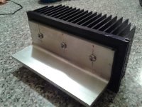
Well after using the amp. I now consider that 54C is slightly too hot for me, I ran some test and much prefer a heatsink around 40-43 C therefore I have invested in a pair of heatsink and some 2 inches right angle bracket. Each heatsink is rated 1 C/W therefore final temp should be around 42C..perfect for MY taste.
Here is a few pic of the work being done.
Rgds,
Eric
Attachments
Heatsink temperature
Hi Eric
54C is just a little too hot for me too. I use my hand to determine the max acceptable temperature. If I can hold my hands more than about 15 seconds on the hottest spot then it meets my criteria since it is safe. It corresponds to less than about 48-50C from experience. With Lateral MOSFET you do not have to worry about temperature for stability.
Since this amp is push-pull you can simply reduce the bias a bit to get lower than 48C if you want to keep the same heatsink. It will simply switch from class A to class AB when close to the max power, that is all. Most surely not audible at that power ...
Fab
Last edited:
Hi Fab,
Thanks for your comments which are always welcome. I have build the ACA with the same heatsink and the ACA works at 19Vdc, biased at 1A therefore Pd is 19W/ch, this new Juma amp must dissipate about 17W/ch so I know it will be running at a temperature very similar to the ACA.
Rgds,
Eric
Thanks for your comments which are always welcome. I have build the ACA with the same heatsink and the ACA works at 19Vdc, biased at 1A therefore Pd is 19W/ch, this new Juma amp must dissipate about 17W/ch so I know it will be running at a temperature very similar to the ACA.
Rgds,
Eric
Nice thick angle bracket.Well after using the amp. I now consider that 54C is slightly too hot for me, I ran some test and much prefer a heatsink around 40-43 C therefore I have invested in a pair of heatsink and some 2 inches right angle bracket. Each heatsink is rated 1 C/W therefore final temp should be around 42C..perfect for MY taste.
Here is a few pic of the work being done.
Rgds,
Eric
Double (or more) the number of bolts to fix to heatsink.
Mount the devices as close to the heatsink as possible, even if it means sawing a bit off the outstanding leg.
All to maximise the heat flow to the sink backplate.
Indeed it's 6mm thick.
The heatsink is 150mm (6 inches), are you suggesting to put a bolt every inch ?
I have never used a L bracket so your comments are welcome.
Thanks,
Eric
The new heatsink looks like it is big enough to handle this 10 watt amp. However, it might be good to use a thermometer and measure your present setup to see what problems you are fixing. What is the temp of the mosfet and the heatsink? Remember, "One test is better than a thousand guesses." If there is more than 10 deg C difference then that interface can be improved. I think you will find that is the second largest bottle neck on heat transfer, next to the heatsink to air. There just is not much surface area. Now considering the big plate on the new heatsinks, I have seen some people actually mill both, but what do they gain for that expense? There is maybe 20 to 40 times the surface area between the plate and heatsink than the mosfet and plate. Is that going to be a bottleneck? Maybe just try the plate the way it is, using good common practices of using a thin coat of heatsink compound and torquing the plate down evenly. I have gotten very little temperature differential that way. Then measure to find out where any heat transfer bottle necks are, if any. I look forward to seeing your finished product and your report on how great it sounds.
Hi,
Thanks for the comments.
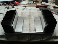
I now have the left channel as before and the right one is set with the new heatsink + L bracket. The left one is still at 54C and the right one is at 43C. This is perfect. The Mosfet + L bracket + heatsink are all about the same temperature, more or less 1-2 degree. I have used a thin coat of heatsink compound to remove the air between both surface and the L bracket is held by 3 screws (10-24) + lock washer. The heat transfer from the Mosfet to the heatsink via the L bracket is working great so it will stay as is.
I'm a happy guy, I'll try to work on the left channel tomorrow.
Pic for fun, new heatsink is on right side. What a messy workplace I have...
Rgds,
Eric
Thanks for the comments.
I now have the left channel as before and the right one is set with the new heatsink + L bracket. The left one is still at 54C and the right one is at 43C. This is perfect. The Mosfet + L bracket + heatsink are all about the same temperature, more or less 1-2 degree. I have used a thin coat of heatsink compound to remove the air between both surface and the L bracket is held by 3 screws (10-24) + lock washer. The heat transfer from the Mosfet to the heatsink via the L bracket is working great so it will stay as is.
I'm a happy guy, I'll try to work on the left channel tomorrow.
Pic for fun, new heatsink is on right side. What a messy workplace I have...
Rgds,
Eric
Attachments
Last edited:
locate the extra bolts down near the knee.
Place them between the transistors so that you can get a big screw driver in through the gap to the head of the posidrive screw.
A bolt would be better since you can torque it up with a spanner.
Instead a much too long screw with a nut put on next to the head.
Then insert the screw until it bottoms and then tighten the nut with a spanner.
This is to try to get as good thermal contact along the edge where the L bracket is hottest.
You have the To3s fairly close to the knee. Any closer and they might ride up the radius of the extrusion and ruin the thermal coupling.
The To3s on the other side cannot ride up the radius, there is none, and the packages can be even closer.
Last edited:
Enclosure
Well I made some progress over the past few days, both channels are in working order and I'm almost done with the enclosure.
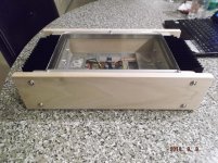
I really enjoy the look of a metal and wood enclosure, this is what I did for this amp. Soon I will add the power switch, RCA, Spkr connector and the DC in connector, wiring everything and as a last step...I will have to varnish the wood. Only then I'll be able to enjoy a new great sounding amp. Thanks Juma ! Hope your move is going smooth.
I will add a led on the front. I added a 6mm thick Plexiglas on top.
Overall size is 14'' W x 8'' D x 4'' H.
Here is a pic for fun.
BR,
Eric
Well I made some progress over the past few days, both channels are in working order and I'm almost done with the enclosure.
I really enjoy the look of a metal and wood enclosure, this is what I did for this amp. Soon I will add the power switch, RCA, Spkr connector and the DC in connector, wiring everything and as a last step...I will have to varnish the wood. Only then I'll be able to enjoy a new great sounding amp.
Thanks Juma ! Hope your move is going smooth.I will add a led on the front. I added a 6mm thick Plexiglas on top.
Overall size is 14'' W x 8'' D x 4'' H.
Here is a pic for fun.
BR,
Eric
Attachments
Last edited:
- Home
- Amplifiers
- Pass Labs
- Recommendation for 5-10W amp.