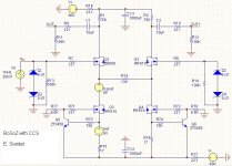
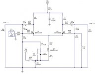
I am planning to build BoSoZ to drive Aleph-X. But since I don't have balance source, I'm going to operate the bosoz unbalanced-in to balanced-out. So, to keep the Vout+ and Vout- equal in magnitude, I replace R3-R6 with CCS. Iref and Iconst were set to be around 40mV, with Iref = 0.67V/R75.
With R75 = 17, Iconst (=Iref) will be approximately 39.4 mA.
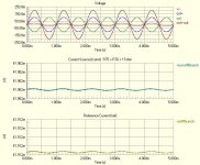
I attached the simm result here, and we can see that the CCS works nicely, so that Vout+ = Vout-. The simm shows the Iref = 41.912mA, and Iconst= 41.962mA.
I run the simm with only one souce (Vs) because I wanted to operate it unbalanced in.
Any sugestion/mods to this circuit? The simm looks OK, but I don't know the result in the real world.
One thing weird about this circuit. I run the simm on Protel DXP, and each time I changed the value of R75 & R76 to, say, 17.5 ohms, the Vout and Iconst swings hecticly. At first, I thought that this circuit was not stable. But, I notice, when I change the value of R75/76 other than 17 ohms, the simm displays a warning: "Gmin stepping failed." What does this mean? I have already change the Gmin parameter before running the simms. Btw, what is Gmin parameter?
Thx folks!
With R75 = 17, Iconst (=Iref) will be approximately 39.4 mA.
I attached the simm result here, and we can see that the CCS works nicely, so that Vout+ = Vout-. The simm shows the Iref = 41.912mA, and Iconst= 41.962mA.
I run the simm with only one souce (Vs) because I wanted to operate it unbalanced in.
Any sugestion/mods to this circuit? The simm looks OK, but I don't know the result in the real world.
One thing weird about this circuit. I run the simm on Protel DXP, and each time I changed the value of R75 & R76 to, say, 17.5 ohms, the Vout and Iconst swings hecticly. At first, I thought that this circuit was not stable. But, I notice, when I change the value of R75/76 other than 17 ohms, the simm displays a warning: "Gmin stepping failed." What does this mean? I have already change the Gmin parameter before running the simms. Btw, what is Gmin parameter?
Thx folks!
Attachments
Assuming that Iref and Iconst are just measurement
points for your simulator, it looks fine.
Z3 and Z4 are superfluous, and there is no need for the
negative supply rail to be so high. 20 volts would be more
than enough. Also you could consolidate the current sources
of Q3 and Q4 into 1 current source, feeding each Source 62
ohms.
Also the negative input should be grounded, so short R14,
the 100K resistor to ground.
Everytime I look, I see something else.....
sianturi said:
Any sugestion/mods to this circuit? The simm looks OK, but I don't know the result in the real world.
I have one like your schematic (sometimes I used a balanced input, sometimes not, so I kept circuitry around the - input).
I've been extremely pleased with the sound using either a single-ended tuner or a balanced D/A converter.
Erik
Nelson Pass said:
Also you could consolidate the current sources
of Q3 and Q4 into 1 current source, feeding each Source 62
ohms.
I see.
I have thought that two sources, however, could provide us with more convenient advanture for gain adjustment, if wanted.
Happy New Year!
The SOZ schematic shows a topology which allows somejh6you said:I have thought that two sources, however, could provide us with more convenient advanture for gain adjustment, if wanted.
adjustment with only one pot. You might consider something
like it.
Nelson Pass said:
Z3 and Z4 are superfluous, and there is no need for the
negative supply rail to be so high. 20 volts would be more
than enough. Also you could consolidate the current sources
of Q3 and Q4 into 1 current source, feeding each Source 62
ohms.
VOILA!! I have already thought of the possibility of using 1 CCS instead of 2, but it never occured to me that the answer is splitting the R15 into 2 x 62ohms.
 Thanks a lot Mr. Pass!
 So here it is, the BoSoZ with one CCS.
A few notes about this circuit. I set R75 = 7.5 and R77 = 100K, so that the value of the Iconst = 80mA (trial and error in simm). Why I pick this number? Cause it is a standard resistor value. I could set the R77 = 15K but then, the R77 has to be 8.375 ohms (non-standard value) in order for Iconst to be 80mA. Is 100K for R77 too big? Is it ok to set it to 100K? :confsed:
I leave the Z3 and Z4 attached for future use if I have a balanced source.
I also use -60Vdc because I plan to use just one transformers (+55V and -55V tap transformer)
Everytime I look, I see something else.....
I hate it when you have that kind of smile....
Another improvement?? :scratch
Attachments
The only thing to remember is that any resistance between the sources of the differential pair will mess up the symmetry of the outputs. You could get rid of the resistors completely, but then you have to find a way to get rid of all the extra gain. Kind of a catch 22 situation, unless you use feedback (which could be cool, because you could apply susy to the circuit).
nobody special said:(which could be cool, because you could apply susy to the circuit).
Btw, SuSy = Aleph CCS, or Susy = X feedback?
I have a thought about applying aleph ccs to this circuit. But I first have to read carefully Mr. Pass' patent about this. I guess this is what the Nelson's smile is all about....

nobody special said:The only thing to remember is that any resistance between the sources of the differential pair will mess up the symmetry of the outputs.
Are you saying that any MISMATCH between the resistors used for source degeneration would 'mess up the symmetry of the outputs'? Or the presence of source resistors in general? Source degeneration is, itself, a form of local feedback.
I'm still not sure if it would lead to "super-symmetry" or just "so-so-symmetry", however.
eL
The presence of them in general...
when driven with a single input and using a balanced output, ideally you should have the sources joined together.
As far as the symmetry of it is concerned, I agree it's not perfect, but the results are better than with the sources coupled through a resistor.
when driven with a single input and using a balanced output, ideally you should have the sources joined together.
As far as the symmetry of it is concerned, I agree it's not perfect, but the results are better than with the sources coupled through a resistor.
Nelson Pass said:
The SOZ schematic shows a topology ...
Thanks. Too often my thinking loses flexibility.
nobody special said:SuSy= X feedback
Here's what I have in mind:
Actually, I have already thought about X-ing this circuit
I have already look at Henrik's X-BoSoZ circuit, and even made a PCB tracks for it (with double CCS). Actually, what I have now is a PCB track which can be used as regular Bosoz (without CCS), Henrik X-BosoZ, and Bosoz with (double) CCS.
To say it in english, regular Bosoz + Bosoz double CCS + Henrik XBosoz in one PCB, so that I can experiment several config.
I guess I just have to rework the PCB....
Attachments
CCS
Hello,
A few months ago, my friend and I also started thinking of
useing CCS in BOSOZ preamplifier, and here below is with
what I come up.
This one is heavily biased, and it would nead for shure larger
heatsink than original BOSOZ.
It is biased at 300 mA per each rail, and is dissipateing 35 W
of heat per channel.
Best regards,
Kristijan Kljucaric
http://web.vip.hr/pcb-design.vip
Attachments
nobody special said:The presence of them in general...
when driven with a single input and using a balanced output, ideally you should have the sources joined together.
As far as the symmetry of it is concerned, I agree it's not perfect, but the results are better than with the sources coupled through a resistor.
What's the mechanism for the degradation, though? I'd have thought that the output impedance of the constant current source would dominate things...
eL
nobody special said:The only thing to remember is that any resistance between the sources of the differential pair will mess up the symmetry of the outputs.
Hmmh.... This one I don't understand also.
Is it because of the presence of the resistor, would destroy the same voltage characteristic between the source of Q1 & Q2 mosfet?
- Status
- This old topic is closed. If you want to reopen this topic, contact a moderator using the "Report Post" button.
- Home
- Amplifiers
- Pass Labs
- BoSoZ with CCS -- need sugestion...