5200 is nice as there's lots of room and only one pcb, and it's interesting to experience what one output transistor can do.
But prob 5400 is a more generally useful Pass experimenter's amp. PS is dual mono for both output stage and input, so there's separate PS for the input section, so there's improvement to be done there as well.
HS on 5400 could be augmented by a piece of ~1/4 inch aluminum plate screwed down to the hs extrusions and spanning across them, if you could live with the appearance. But you will get addicted to more and more bias, and it will be set to a zone between your comfort level of how hot a transistor should be and the thermal switch shutting it down. And then you start thinking about putting a fan on it, when instead you should be building an F5....
Hey Guys
OK, so I just ordered the big 47k 35V caps for the 5400.
Thanks for the help and the links to those caps.
And while I was at it I got a set of fresh caps for the gfa-535II.
(did Mr. Pass design that one too)?
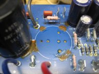
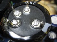
BTW, does anyone know what this brown dried up goo is on the power supply boards? Its pretty much under each electrolytic cap on the power supply board.
To me it looked like it was a leaking Electrolytic cap but upon removing one of those caps, it does not look like it coming from the cap.
Here is a photo or two to show what is going on.
Thanks again
Curt
OK, so I just ordered the big 47k 35V caps for the 5400.
Thanks for the help and the links to those caps.
And while I was at it I got a set of fresh caps for the gfa-535II.
(did Mr. Pass design that one too)?
BTW, does anyone know what this brown dried up goo is on the power supply boards? Its pretty much under each electrolytic cap on the power supply board.
To me it looked like it was a leaking Electrolytic cap but upon removing one of those caps, it does not look like it coming from the cap.
Here is a photo or two to show what is going on.
Thanks again
Curt
Attachments
BTW, does anyone know what this brown dried up goo is on the power supply boards? Its pretty much under each electrolytic cap on the power supply board.
To me it looked like it was a leaking Electrolytic cap but upon removing one of those caps, it does not look like it coming from the cap.
That goo is an adhesive they use to attach the caps to the board. My PS board also had the goo. Your board is a different version than mine. My board is green where yours is blue and yours offers the more flexible 22.5mm LS 4 pin in addition to the 10mm LS 2 pin capacitor mounting configuration. This is a good thing because I just realized the 47k uF caps I linked to were a 4 pin 22.5mm LS like the ones your board has. When I did my search at Mouser I picked 10mm LS as one of the search options, I guess that 22.5mm LS cap got added to my search for some reason. Anyway, they'll work great for you. Anyone that reads this and is thinking about purchasing those caps you need to turn your PS board over and verify whether your board uses a 2 pin capacitor or the more flexible 2pin & 4 pin capacitor mounting scheme. If its the 2 pin only then you will have to find a 35mm diameter X 10mm LS 2 pin capacitor. As stated earlier, the color of the board may denote which version it is as well, but you cannot rely completely on that.
Last edited:
Hi all,
I have a GFA5400 serial#00110 and the right speaker has a soft hum, that can be heard very faintly up to 1 meter from the speaker, from all three drivers in the speaker enclosure and the left speaker is dead quiet. I moved the right channel speaker wire to the left speaker and the left channel speaker wire to the right speaker. The hum moved to the left speaker and the right speaker is dead quiet. turning up the pre amp volume knob did not increase the hum loudness. I removed the interconnects from the pre amp to the amp and did the same switching test and results were the same. That, to me, indicates a problem in the amp's right channel. If anyone agrees with this test , what may be causing the problem?
Thanks,
henrylrjr
Prob old PS caps.
Connect amp to cheap test speakers. Take off the cover and give the 2 large PS caps on the humming channel a whack to see if the hum changes. If it doesn't change, pull all 4 rail fuses, and then measure the PS ripple in mVAC on the 4 rails for the output stage (and the 4 rails for the input stage, for reference). Don't cause a short. If one has much higher ripple than the others, then it's prob a dry PS cap.
Connect amp to cheap test speakers. Take off the cover and give the 2 large PS caps on the humming channel a whack to see if the hum changes. If it doesn't change, pull all 4 rail fuses, and then measure the PS ripple in mVAC on the 4 rails for the output stage (and the 4 rails for the input stage, for reference). Don't cause a short. If one has much higher ripple than the others, then it's prob a dry PS cap.
Thanks for the advice. I happen to have a 6 inch driver from an old speaker with no enclosure or xover. Would that work for the test? If so it should be dead quite connected to the left amp output and humming when connected to the right output. If that works then I could try whacking the right side PS caps.
Are the PS caps in the GFA5400 solder or twist in caps? I'm new to working on amps or preamps. Just familiar with xovers I've made where everything was soldered and caps rarely exceeded 47uf.
thanks,
henrylrjr
They are soldered in! See my post #24. Just be careful with those old posts as we were talking about lowering the rails and using 35vdc rated caps. The original main PS caps are 63V rated and my rails were about 61V under load so these caps do not have a lot of headroom. You might want to see if you can move up to a 75V cap. There is a lot more height available so you may find some tall replacement caps, a bit more capacitance wouldn't hurt either.
Last edited:
I just recapped a 5400, and I used these now-obsolete but perfect fit 18mF 63V 4-pin Panasonics from Mouser:
ECE-T1JP183EA Panasonic | Mouser
Same size, different series, Mouser pn 667-ECE-T1JA183EA:
Get 4 before they run out as well (37 in stock). $10 each.
ECE-T1JA183EA Panasonic | Mouser
ECE-T1JP183EA Panasonic | Mouser
Same size, different series, Mouser pn 667-ECE-T1JA183EA:
Get 4 before they run out as well (37 in stock). $10 each.
ECE-T1JA183EA Panasonic | Mouser
Currently on ebay there's a Stan Warren modded 5400: "which was custom modified by Stan Warren two years ago. He replaced some of the mosfet devises with super fast toshiba high current transisitors along with many other internal modifications. He felt that this was his best sounding modified Adcom. On the outside Vampire RCA’s, Furutech IEC and Gold binding posts were added. This amp sounds smooth yet detailed with allot of slam."
The pics appear to show one of the original IRFP240 Mosfets in parallel with a Toshiba 2SC3281 NPN (and similarly on the negative V rail, an original IRFP9240 Mosfet in parallel with a Toshiba 2SA1302 PNP) and one of the original Mosfets left out. It appears the Base of the 2SC3281 (in position Q618) is connected to the Source of the IRFP240 in position Q620) with an additional link (and similar connection on the -V rail).
What's going on there? Mosfets paralleled with BJT?
Adcom 5400 Amplifier Custom Modified 811900010002 | eBay
This was no joke: This amp on ebay appears to have output mosfets paralleled with BJT! Why would someone do that? What would happen? And here I am, obsessing over matching parallel mosfets, while someone is mixing mosfets and BJT?!

Hello Folks - resurrecting an old thread about modding an Adcom 5400.
I had to step away from the whole DIY thing for quite awhile and now am back
warming up the soldering iron trying to finish up the first mods to an Adcom 5400.
I am going the half voltage route to reduce power dissipation to effectively make the heatsinks bigger.
So I just soldered in new power supply caps (47,000uF @ 35V each) and the next step is to put the
primaries of the transformer in parallel to lower the rail voltage out of the secondary of the transformer.
Before I go ahead and do this, I'd like to ask, how is that best accomplished?
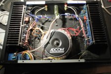
Here are three photos, first one showing the version of the amp I have.
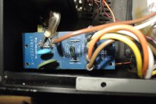
Second one shows the voltage selection pc board where I believe the changes need to be made.
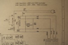
Third photo is of part of the power supply schematic that I have for reference.
I dont know if this schematic is actually for this version of the amp (schematic says Version 1 in the title box)
and thats why I am a bit hesitant to proceed without help.
It looks like all I need to do is remove two jumpers and add another.
Plus remove C922 which quite frankly, I dont know what kind of device that is.
To finish the conversion, I guess I need to add C923 which is different than C922.
Anyway, log post here, sorry. Any help, greatly appreciated.
Curt
I had to step away from the whole DIY thing for quite awhile and now am back
warming up the soldering iron trying to finish up the first mods to an Adcom 5400.
I am going the half voltage route to reduce power dissipation to effectively make the heatsinks bigger.
So I just soldered in new power supply caps (47,000uF @ 35V each) and the next step is to put the
primaries of the transformer in parallel to lower the rail voltage out of the secondary of the transformer.
Before I go ahead and do this, I'd like to ask, how is that best accomplished?
Here are three photos, first one showing the version of the amp I have.
Second one shows the voltage selection pc board where I believe the changes need to be made.
Third photo is of part of the power supply schematic that I have for reference.
I dont know if this schematic is actually for this version of the amp (schematic says Version 1 in the title box)
and thats why I am a bit hesitant to proceed without help.
It looks like all I need to do is remove two jumpers and add another.
Plus remove C922 which quite frankly, I dont know what kind of device that is.
To finish the conversion, I guess I need to add C923 which is different than C922.
Anyway, log post here, sorry. Any help, greatly appreciated.
Curt
Attachments
Thank you Nelson for the clarification.
Yeah I got it backwards, meant to say in that for this modification,
the primaries go in series. Its an important detail
Does anyone know what devices C922 or C923 in the schematic in my post just above are? I have no idea what they are.
C922 is present as the amp is set up for 120V operation.
For 240V setup C922 gets removed and C923 is installed instead.
Problem is, I do not have that that part and need to identify it.
Anyone know what they are?
Thanks again
Curt
Doesn't wiring the primaries in series effectively halve the VA rating of the transformer?
If we are just doing that, then there is no problem since all we are doing is reducing the amplifier's power.. but making the thing class A and ramping bias up might get you in trouble.
Please tell me i'm wrong, if I am
If we are just doing that, then there is no problem since all we are doing is reducing the amplifier's power.. but making the thing class A and ramping bias up might get you in trouble.
Please tell me i'm wrong, if I am
Quote - Doesn't wiring the primaries in series effectively halve the VA rating of the transformer?
Wow, that never even occurred to me. I wish I knew the answer to that, perhaps someone else can chime in.
One other thing that occurred to me, the idea behind all of this is to lower the power dissipation of the output stage
by lowering the rail voltage that the output stage sees and thus effectively increasing the heatsink area to allow tuning up the bias.
But....this scheme also lowers the rail voltage to the input stage and driver stage. Are there negative consequences to this?
Curt
Wow, that never even occurred to me. I wish I knew the answer to that....
...
But....this scheme also lowers the rail voltage to the input stage and driver stage. Are there negative consequences to this?
Curt
That IS the answer, sort of.
Like ZM said, without saying; if the traffo is overbuilt with a larger than necessary core and with secondaries that are over sized then all is well.
But if the secondaries are rated to deliver, say, 10 amps at 40 Volts - then they are still only rated for 10 amps at 20 Volts. The wire is still the same size.
VA = V x A
No idea on the amp's circuit.
- Status
- This old topic is closed. If you want to reopen this topic, contact a moderator using the "Report Post" button.
- Home
- Amplifiers
- Pass Labs
- Some questions on an Adcom 5400