Better than nothing. And remember, the bulb must be incandescent. Florescent or LED won't help you.
Thanks Jim. I will go look for a 100W bulb if it way better than 57W. ;-)
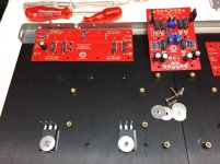
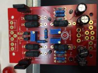
F5T amp building is progressing well. I started with the front end PCB and have completed putting on the components. Whilst checking against what Jim has, I realized that my PCB has Q7 and Q8 instead of Q5 and Q6 respectively. I can't confirm if I have shorted the C-E correctly as the PCB doesn't indicate the B-C-E. Scouring at the Internet, I mapped it based on the diagram here:
20180325_174315_1.jpg - Google Drive
20180325_174322_1.jpg - Google Drive
Let me know if this is right. TIA
20180325_174315_1.jpg - Google Drive
20180325_174322_1.jpg - Google Drive
Let me know if this is right. TIA
A question about wire gauge. Do you just use what will fit or is there specific gauges that are to be used in certain areas such as ac inout etc?
I will always try to find the wires which will fit the holes; if not, i will thin them till they fit. :-D
Building an F5 Turbo v2 (in-Progress)
V2 stereo is pretty much the same as V3 monoblock reffering to heatsink requierements etc.
V2 stereo is pretty much the same as V3 monoblock reffering to heatsink requierements etc.
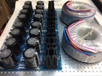
PSU requirements
Thanks, 6L6, for this detailed build guide, which got me started in this project.
I am currently building an F5T V2 and have some newbie questions on the power supply:
"A stereo F-5T v2 requires a bipolar power supply of (+/- 32V). This will require an 24V+24V (or 48V Center Tapped) transformer from 600-800VA, and PSU capacitance of 80,000uF per rail or more."
What exactly is the rail? One half of the PSU (4 capacitors) or the full PSU (8 capacitors)? I have 15000 uF / 50V Nichicons on stock.
Is it overkill to use 2 transformers (400 VA each) and 2 PSUs (e.g. 120000 uF each)? Are there any advantages?
With 30V AC on the transformer side and 40 V DC on the PSU side do I have to make changes on the FE board?
Please advise - and many thanks for supporting us less experienced builders out there.")
Best, Markus
Thanks, 6L6, for this detailed build guide, which got me started in this project.
I am currently building an F5T V2 and have some newbie questions on the power supply:
"A stereo F-5T v2 requires a bipolar power supply of (+/- 32V). This will require an 24V+24V (or 48V Center Tapped) transformer from 600-800VA, and PSU capacitance of 80,000uF per rail or more."
What exactly is the rail? One half of the PSU (4 capacitors) or the full PSU (8 capacitors)? I have 15000 uF / 50V Nichicons on stock.
Is it overkill to use 2 transformers (400 VA each) and 2 PSUs (e.g. 120000 uF each)? Are there any advantages?
With 30V AC on the transformer side and 40 V DC on the PSU side do I have to make changes on the FE board?
Please advise - and many thanks for supporting us less experienced builders out there.
Best, Markus
Forgot to mention that it is the Universal PSU sold at the DIY Audio Store.
And yes the input board is cascoded.
Has anyone used this produt before as thermal pads for power transistors?
Warmeleitfolie 0.5 mm 6 W/mK (L x B) 50 mm x 50 mm Kerafol 86/600 kaufen
It is based on something like soft (silicone) rubber, seems to have a good thermal conductivity at 6W/mK and originates from the same manufacturer than the Keratherm foils offered in the shop.
Forgot to mention that it is the Universal PSU sold at the DIY Audio Store.
And yes the input board is cascoded.
Has anyone used this produt before as thermal pads for power transistors?
Warmeleitfolie 0.5 mm 6 W/mK (L x B) 50 mm x 50 mm Kerafol 86/600 kaufen
It is based on something like soft (silicone) rubber, seems to have a good thermal conductivity at 6W/mK and originates from the same manufacturer than the Keratherm foils offered in the shop.
If I remember correctly, you should buy the Kerafol 86/82. Conrad has them also.
Hi,
Great build guide, thanks. Planning a f5tv2 NOT cascoded, with 32V rails.
There was a lot of discussion at the beginning about not mounting the mur diodes on the same heatsink so as to prevent thermal runaway. But the guide,and everyone else seems to be mounting everything on the same sinks. So what's the consensus?
You should just cascode to protect the JFETs as the operating voltage for these are ~25V max. After contemplating for a while, I decided to do it for the ease of mind. No point wondering when they will breakdown given they are so rare these days.
Use a 5U chassis, ventilate well and not to bias too high (I did 0.3V being a fraidy cat) - I think you should be fine.
Use a 5U chassis, ventilate well and not to bias too high (I did 0.3V being a fraidy cat) - I think you should be fine.
You should just cascode to protect the JFETs as the operating voltage for these are ~25V max. After contemplating for a while, I decided to do it for the ease of mind. No point wondering when they will breakdown given they are so rare these days.
Use a 5U chassis, ventilate well and not to bias too high (I did 0.3V being a fraidy cat) - I think you should be fine.
Thanks.
I am not sure what you mean by operating voltage. The breakdown voltages (gate-drain, gate-source) are 40V each, which I should think leaves enough headroom with 32V rails.
Still not sure about the MUR diodes on the sinks though.
...
The breakdown voltages (gate-drain, gate-source) are 40V each, ...
They are???
An externally hosted image should be here but it was not working when we last tested it.
Place diodes on same heatsink as Mosfets.
I strongly suggest cascoding if you use 32v rails.
Last edited:
I am currently building an v2 using a total of 2 Diyaudio universal PSU boards so to have a
CRCCRC Filter. For wiring reasons I would like to take the power for the front end boards after the first PSU board, and the Output boards from the final C on the second board.
As long as I return all grouns to my main audio ground it should'nt have issues, but I am not afraid of asking stupid questions.
Anyway, thanks in advance for your help.
- Home
- Amplifiers
- Pass Labs
- F5Turbo Illustrated Build Guide