to ItsAllInMyHead #897
Good evening!
Hello ItsAllInMyHead, the values in posts ##886/887 are in the ballpark.
My F5T has a similar difference in the bias voltage from the N-ch to the P-ch-Mosfets. My voltage over the bias resistors are also around 20mv different.
Nothing to worry about. I have the same in my BA-3 poweramps. And my Mosfets have also been matched with care.
Keep your DCoffset over speakeroutput below 50mV (below 10mV is good,
below 1mV really good). I would use this amp for a week (if possible with cheap speakers). After one or two weeks listening with the amp I would recheck the DCoffset (after a warmup-time of minmum 20-30minutes).
If you listen to this new amp and you hear any unusual noise - better shut down and check.
But I think it is time to listen to some music!")
And please: first switch on the source
then the preamp
then the F5T.
if you switch off: first the poweramp
then the premamp
then the source.
Greets
Dirk
p.s.: Sorry for my late response - I was a bit busy this weekend.
Good evening!
Hello ItsAllInMyHead, the values in posts ##886/887 are in the ballpark.
My F5T has a similar difference in the bias voltage from the N-ch to the P-ch-Mosfets. My voltage over the bias resistors are also around 20mv different.
Nothing to worry about. I have the same in my BA-3 poweramps. And my Mosfets have also been matched with care.
Keep your DCoffset over speakeroutput below 50mV (below 10mV is good,
below 1mV really good). I would use this amp for a week (if possible with cheap speakers). After one or two weeks listening with the amp I would recheck the DCoffset (after a warmup-time of minmum 20-30minutes).
If you listen to this new amp and you hear any unusual noise - better shut down and check.
But I think it is time to listen to some music!
And please: first switch on the source
then the preamp
then the F5T.
if you switch off: first the poweramp
then the premamp
then the source.
Greets
Dirk
p.s.: Sorry for my late response - I was a bit busy this weekend.
Hi Dirk!
Thanks for confirming realistic readings once it's all stable.
Given the new information in post #898 re: the odd behavior of the right channel, there may still be some investigation to do. I admit, I'm stumped. I looked at the new readings Dennis suggested in #899 / #900. Along with #898, it looks like something weird around Q6, but I just can't work it out.
Edited for fat fingers to correct post numbers.
Last edited:
I forgot: minor fluctuations in the DCoffset are pretty normal (my experience with the F5T as well with the BA-3). If it fluctuates anywhere below 5mV - I wouldn't worry. I think most of this is caused by thermal drift of parts (especially trimpots) as well from regulation in the the circuit.
The thermistors should have good thermal contact to the plasticcase of the Mosfet. I used a thermal compound / glue (I don't want to advertise any brand...
the computer guys use it to glue cooling fins / heatsinks on CPUs - arct.. silver
or keraf.l or....)
Greets
Dirk
The thermistors should have good thermal contact to the plasticcase of the Mosfet. I used a thermal compound / glue (I don't want to advertise any brand...
the computer guys use it to glue cooling fins / heatsinks on CPUs - arct.. silver
or keraf.l or....)
Greets
Dirk
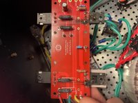
So Sundays have just became a day of expressing. Expressing you may ask? Expressing how beyond pissed off i am at my F5T. The left channel, the one that blew up last week after all of the new mosfets were installed was in my opinion the more stable of the (2) channels. The bias pretty much held steady since it was fired up yesterday. After it warmed up, I tweaked it slightly this morning and the offset was -5mv holding pretty much all day. Before I’d connect any speakers to it, I was going to run a sign wave with an 8 ohm dummy load and my scope on the output to see what things looked like. Everything is connected up and I turned the power switch. Instantly smoke, fire and more blown output fets. Not sure what to do. The only thing that changed from it running idle all day with the input shorted was now the input wasn’t shorted and there is an 8 ohm dummy load on the output. Any thoughts?
Attachments
Last edited:
Patrick and Dirk, originally I thought the same about the load being shorted out. Not the case at all, I checked and it’s fine. Then I thought the signal generator or something with the scope, that’s totally fine at least when I run them independently. As for the torque, I tightened the MOSFETS but gosh, not that tight. Basically snug with lock washers on them. I have not plugged or unplugged anything with the amp on. The only thing is the amp was fine for about 10 minutes while I connected everything up. Unfortunately I disconnected all of my meter leads so I don’t know if the bias took off at start up like it did this morning. The signal generator was powered up and I didn’t realize it was giving a 5V sine wave output voltage at 1khz when I turned on the amp. As for too much bias, it was running at 345mv’s all day and the sinks were not excessively hot at all. Could the high input signal at startup have caused this but why only the left channel again and not the right?
Elwood, I’m using the ones that come in the kit from the store SDUR60P60DT/SSG18441
Elwood, I’m using the ones that come in the kit from the store SDUR60P60DT/SSG18441
Last edited:
Did you by any chance call the amp names? I am starting to think this amp is after revenge. Certainly treats some owners that way...
You could give up, and build the BA-3 like me. Damn stable amp, can really take a beating. I made plenty of mistakes, and have not been punished severely.
Wrt your last post: I believe Dirk and Itsall are not saying the load itself was shorted. They are, as I understand, implying that an existing short in your amp was completed when the dummy load was connected to the positive and negative outputs.
5v sinewave, that might explain it... dunno.
You can measure resistance between the center pin of the fets and the sink to provide som insight. It should be in the thousands of ohms range. If not, do not proceed until solved. If there was damage to the sink after the first blow up, be sure to make the surface even again. Use a magnifying glass, small bits of metal can cause such shorts, protruding from the metal and piercing the thermal pad and gaining contact with the fet.
Maybe a silly question: but did you reuse any of the thermal pads after the first blow up? Was there any damage to the sink?
I have empathy for your situation. As you can see from my signature, I had a small fire too. And some other issues. But a channel blowing up is the worst I can imagine.
And, I am NOT an expert, just trying to help best I can.
Good luck, man!
Last edited:
So Sundays have just became a day of expressing. Expressing you may ask? Expressing how beyond pissed off i am at my F5T. The left channel, the one that blew up last week after all of the new mosfets were installed was in my opinion the more stable of the (2) channels. The bias pretty much held steady since it was fired up yesterday. After it warmed up, I tweaked it slightly this morning and the offset was -5mv holding pretty much all day. Before I’d connect any speakers to it, I was going to run a sign wave with an 8 ohm dummy load and my scope on the output to see what things looked like. Everything is connected up and I turned the power switch. Instantly smoke, fire and more blown output fets. Not sure what to do. The only thing that changed from it running idle all day with the input shorted was now the input wasn’t shorted and there is an 8 ohm dummy load on the output. Any thoughts?
Missed your pics.. sorry.
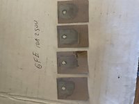
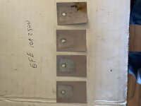
I think Dirk is referring to the black burn mark on one of your Keratherms. Looks like a short, yea.
Hi Andy, many names after the smoke flew. And then my wife walks in from outside and says, “are you burning rubber or something in here?” Almost more names flew but I held my tongue lol! There does not appear to be any heatsink damage. This time there is some carbon which will need to be cleaned. I did reuse the thermal pads but they were clean. Not like the pic this time, those are shot from today’s event. As for a difference between the input shorted or not shorted, I don’t know, I never checked it. I understand what your saying that possibly I completed a short by connecting the output. I misinterpreted their suggestions but I also had checked the load because that was one of the 2 things that changed. I appreciate everything anybody offers. It’s a learning process for sure.
Hopefully even this moody amp is not into preemptive revenge...
A question wrt when what was done: at what point did you solder the new fets? Before or after tightening it to the sink, and dis you wait until the output boards where fastened with bolts? It looks like the burnt trace indicates a crooked fet.
I usually tighten the fet first, then the board, then solder.
Regards,
Andy
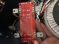
The picture of the reverse side of the board shows the thermal pad stuck to the back of the diodes, heat for a long period of time, relative to the MOSFETS. Considering you melted the metal pin off the MOSFET, localize excessive marks on the thermal pad I would expect. Very hot, very fast.
Remove the other board and see if those diodes have the thermal pad stuck to the back.
Remove the other board and see if those diodes have the thermal pad stuck to the back.
luvrockin -
Glad to hear it wasn't the load resistor setup. Ask me how I know that can happen.
re: the signal generator => 5V post #909.
Going back to Dennis' excellent post #851
Unless anything else obvious rears its head. I'd say that's at least a chunk of the contributing cause. However, I don't know how it would behave at 2+ times the clipping voltage while the bias is stabilizing. Others will need to verify or please let me know if that's way off the mark.
After you've had whatever beverage(s) you may need to get back in the saddle, send me a note. I may have another set I can send you. In the interim, you can sort out that right channel.
As always... I can put out thoughts, but wait for someone with actual knowledge to confirm if that's a likely contributor to the situation or if you should also look at anything else in addition.
I don't know who votes and hands out the badges, but you're definitely a nominee for the FAB club as far as I'm concerned.
Last edited:
Nice one, Itsall. And as Luvrockin mentioned in an earlier post, startup bias current was allready well above diode conductance values. Add 5 volts in, might be it. Still a real bummer.
Which begs the question: should the bias current ever be allowed to be so high that the diodes conduct, even at startup? Dirk or Dennis I believe said «no» in an earlier post. If so, that is another issue that might need solving. Still, seems a bit odd the blowup was immediate because of this. I would expect it to at least take some seconds...
What a community! Helping each other out, even sending fets when people are in need. Really cool!
Last edited:
I was past editing time for my post above. I was re-reading when I noticed below...
Andy...
luvrockin -
I assumed you only had the left channel hooked up while we were all still wondering about the right channel wavering. Did you have both channels connected to the signal generator at the same time? If so, how? Dual output signal generator? Load resistors on both channels? Just need to ask. More data is better.
Andy...
luvrockin -
but why only the left channel again and not the right?
I assumed you only had the left channel hooked up while we were all still wondering about the right channel wavering. Did you have both channels connected to the signal generator at the same time? If so, how? Dual output signal generator? Load resistors on both channels? Just need to ask. More data is better.
Patrick, fully agree, the more info input, the better information out. Yes, a dual output generator connected to right and left channel input and a dual channel oscilloscope with one probe connected to the left channel 200w/8ohm resistor and the other probe on the other channels load resistor. But same condition with the output of the signal generator accidentally sending 5V input signal. I just think if that was the issue, I would’ve smoked both channels at start up?
- Home
- Amplifiers
- Pass Labs
- F5Turbo Illustrated Build Guide