I would take Patrick's offer of MOSFETs.
The bias current at startup will be higher than the final bias point. This is due to the thermistors, which have higher resistance when cold (and thus total MOSFET biasing voltage is higher).
You have to ensure that the diodes never, ever conduct with any possible DC biasing condition, including the higher bias at startup.
The colder your environment gets, the higher the startup current and the delta between it and the final bias.
Patrick & Sangram, thank you so much. I really appreciate it. Patrick, I will pm you in a bit. What is meant when you mention current hogs?
Sangram, this morning I fired the amp up and my bias was at 360mv/-20dcmv offset at start up and within a couple minutes it was down to 335mv/-1.2-.2dcmv offset. I think it’s ok.
Just so I’m doing this correctly, I bought a signal generator (nothing fancy) but I just connect that to my input, correct? Should I set that at about .8v out at 1khz? Secondly, I just attach my oscilloscope across + & - speaker out to see the wave and gain?

Patrick & Sangram, thank you so much. I really appreciate it. Patrick, I will pm you in a bit. What is meant when you mention current hogs?
Excellent. Reply in your inbox.
The way my brain tries to understand it...
When you have two devices in parallel with the same input voltage at the gate, you want them to turn on at precisely the same time (taken care by sufficient bias in this case, so not as much of a worry). If one device turns on at 4V4 and the other at 5V2, that's not great.
You also want them to share current equally through the drain and source, Ids at the given voltage. So, if the devices aren't matched, one device would draw more current than the other. Source resistors take care of some of that, and we're not talking about much. However, tighter matches are better to ensure even thermal balance between parts and good operation.
As is usual, I know brighter minds will chime in if I've got it all wrong. This is just how I think it works ....

Edited to add - in practice I just measure the voltage across each source resistor to see if there are any little piggies.
Also changed roughly to precisely... they should start to conduct exactly at the same time.
Last edited:
Sangram, this morning I fired the amp up and my bias was at 360mv/-20dcmv offset at start up and within a couple minutes it was down to 335mv/-1.2-.2dcmv offset. I think it’s ok.
I believe you have to wait much longer, I`d re-adjust bias when heatsinks are at around 50C.
Just so I’m doing this correctly, I bought a signal generator (nothing fancy) but I just connect that to my input, correct? Should I set that at about .8v out at 1khz? Secondly, I just attach my oscilloscope across + & - speaker out to see the wave and gain?
Be very careful when testing with a signal generator. If you put the wrong square wave frequency (i.e. high enough) it may fry the output devices.
Mario, thank you for the valuable input. I had the bias set at about 330mv yesterday after the amp had been running all day. It was later in the evening when I turned it off and rechecked it later. That when it seemed like the bias was much higher than when originally set. Shortly after I turned the amp off. This morning I turned it on and again the bias was higher than originally set but shortly after (within a couple few minutes) it dropped down and has been holding pretty constant all day and the offset has been hovering right around the 0vdc range. I had no idea about the signal generator. I just wanted to play/learn a bit. I did give a 1khz test sine wave signal. I just wasn’t sure what a good input voltage is to give the amp. I’d like to see how much it boost that signal. Is .8v ok or should it be higher?
Joe
Joe
Excellent. Reply in your inbox.
The way my brain tries to understand it...
When you have two devices in parallel with the same input voltage at the gate, you want them to turn on at precisely the same time (taken care by sufficient bias in this case, so not as much of a worry). If one device turns on at 4V4 and the other at 5V2, that's not great.
You also want them to share current equally through the drain and source, Ids at the given voltage. So, if the devices aren't matched, one device would draw more current than the other. Source resistors take care of some of that, and we're not talking about much. However, tighter matches are better to ensure even thermal balance between parts and good operation.
As is usual, I know brighter minds will chime in if I've got it all wrong. This is just how I think it works ....
Edited to add - in practice I just measure the voltage across each source resistor to see if there are any little piggies.
Also changed roughly to precisely... they should start to conduct exactly at the same time.
A huge shout out to Patrick and Jim 6L6 for the major bailouts with parts needed in a pinch. Thank you guys for all and the rest of the forum for the support. This group has been great.
Joe
I’d like to see how much it boost that signal. Is .8v ok or should it be higher?
Joe
If I'm understanding the schematics correctly, the gain should be about x12.
An input of 0.8V should give you under 10V output. That's a decent
output that should be easy to see/measure on your scope.
Dennis is a math and circuit guru. Last part of the equation is 0v8 x 12 = 10-ish volts out. But I thought the gain of the Turbo was approx 20db iaw reduced feedback.
But anyways, sorry to hear about the blow-up. Take comfort in the fact that you are not alone!
Every day that goes by makes me wanna build this amp less and less. It is moody as a drag queen in menapause.
But anyways, sorry to hear about the blow-up. Take comfort in the fact that you are not alone!
Every day that goes by makes me wanna build this amp less and less. It is moody as a drag queen in menapause.
Thank you, don’t quite understand where you came up with the 12. This amp has been cooking all day, at least half of it and it looks like I’m stumbling on something else. My bias really seems to be fluctuating a lot. Not sure if this is normal or not.
Andy, btw, love the adjective
Andy, btw, love the adjective
Last edited:
Fluctuating bias can be caused by the thermistor contacting the steel fender washer instead of the plastic body of the MOSFET. Also, the paint on the thermistor is known to short out output devices when it is in contact with metal surfaces.
One of the few failures I have avoided, there are several posts in this and the F5 thread regarding this issue.
One of the few failures I have avoided, there are several posts in this and the F5 thread regarding this issue.
Thank you Elwood625, that could be my issue. I have my thermistor actually touching the washer and put some heat transfer compound between it. Jim 6L6 mentioned it not touching as well and I totally forgot about changing that. Are you saying the thermistor should touch the MOSFET housing?
Curious where the best spot to attach power to the front plate power LEDs on the boards will be? There are two on the PSU, should I run a couple wires from there?
Also, is there a nice way to attach the LEDs to be back of the faceplate so they glow nicely instead of shine through at an angle like a flashlight?
Also, is there a nice way to attach the LEDs to be back of the faceplate so they glow nicely instead of shine through at an angle like a flashlight?
Mrdrewk - Use the LED location on the power supply. One idea is to drill a 1mm hole, then with the LED up against the hole.
I used a scrap piece of wood to find the right size hole for the LED I was using, then I drilled the front panel accordingly. I still use a large resistor to dim the LED's I use. I prefer mood lighting to aircraft landing lights.
I used a scrap piece of wood to find the right size hole for the LED I was using, then I drilled the front panel accordingly. I still use a large resistor to dim the LED's I use. I prefer mood lighting to aircraft landing lights.
@luvrockin: The gain is approximately 1 + (resistance of (R7 parallel with R8)) / R3)
Speaking the thermistor, has anyone used one with a mounting lug?
https://www.mouser.ca/datasheet/2/427/ntcalug02a-1762595.pdf
Speaking the thermistor, has anyone used one with a mounting lug?
https://www.mouser.ca/datasheet/2/427/ntcalug02a-1762595.pdf
I swapped in the 1% (why not) part on the standard F5 just for fun and maybe a bit of peace of mind.
New Part
mfr - NTCALUG02A472F
Mouser - 594-NTCALUG02A472F
That part was recommended on the F5 thread. I was also going to link it here, but I could not find a max power rating listed anywhere for the part to compare against the 450mW rating of my original part. I am not sure how to calc the expected current during startup or speculate what it might be in a failure mode. Operating current in situ on the F5 at ballpark temp of 45C (Ravg - 2052) was reasonable to me. I measured the voltage drop and got what I recall to be an inconsequential number.
Anyone that knows how to do this properly to ballpark worst case current/power in the F5T and can share would have my admiration. It may just be as easy as "Fuggetaboutit" it's so low as to be boring.
Old part for comparison
Mfr - B57164K0472J000
Mouser - 871-B57164K472J
Digikey - 495-2082-ND
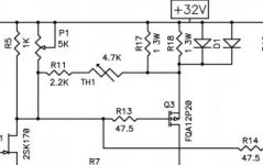
I think the dissipation across the thermistor is fairly low, say less than 8mW.
(Hope I did this correctly.)
I've attached a snippet of the schematics. The power through the
thermistor comes from the voltage drop from R11 through the thermistor
to the source resistor of the mosfet. This voltage drop is just the Vgs
voltage of the mosfet. Without a signal, this Vgs is probably in the 4-ishV
range. With a signal swinging the max output of the amp, it can go
up to 6-ish volts. So let's be conservative and say 8 volts.
If R is the resistance of the thermistor, then the max current is less than
I = 8/(2210+R) and the dissipation of the thermistor is
I^2 * R < (64*R)/((2210+R)^2 ). This max is less than 7.3mW
across the operating resistance range of the thermistor.
Attachments
- Home
- Amplifiers
- Pass Labs
- F5Turbo Illustrated Build Guide