The cap orientations on the FE board seems ok when I compared them to a photo of the
unpopulated board here:
https://cdn.shopify.com/s/files/1/1006/5046/products/F-5T1_1024x1024.jpg?v=1455100508
unpopulated board here:
https://cdn.shopify.com/s/files/1/1006/5046/products/F-5T1_1024x1024.jpg?v=1455100508
luvrockin,
I may have missed it but do you have any voltage measurements you can post?
I'm not familiar with the F5t but looking at the schematics I would
suggest measuring the voltages across R25, R26, R27, R28, R3, R4, R5, R6 as well as the DC offset.
With P1/P2 low and the output stage off you may see the cascode transistors to run a little bit
hotter, both from the unloaded rails, but also from higher voltage across the collector
and emitter. But you should still be dealing with a fraction of a watt.
R25, R26, R27, R28 should all have the same resistance with +/-32V rails. 10K or 4.75K for all of them. Then you end up with around 16V to the J-fets.
Rail voltage / (R25+R27) * R27 = cascode voltage.
32V / (10+10) * 10 = 16V
32V / (4.75+4.75) * 4.75 = 16V
32V / (10+4.75) * 4.75 = 10.3V
32V / (4,75+10) * 10 = 21,7V
As it sits, your cascode voltage is around 10.3V.
Rail voltage / (R25+R27) * R27 = cascode voltage.
32V / (10+10) * 10 = 16V
32V / (4.75+4.75) * 4.75 = 16V
32V / (10+4.75) * 4.75 = 10.3V
32V / (4,75+10) * 10 = 21,7V
As it sits, your cascode voltage is around 10.3V.
to luvrockin
Hello luvrockin,
andynor, Dennis Hui and Audiosan were faster. Sorry for my late response!
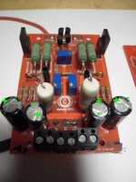
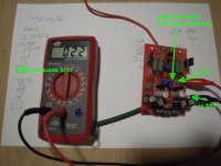
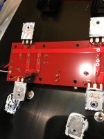
I show you pics from one of my frontends.
Your caps seem to be oriented right.
P3 is adjusted to mid position?
Solderbridge between 'link' and 'G' (ground) is done.
cables from frontendboard to P-channel-board and to N-channel- board seem o.k..
Greets
Dirk
Hello luvrockin,
andynor, Dennis Hui and Audiosan were faster. Sorry for my late response!
I show you pics from one of my frontends.
Your caps seem to be oriented right.
P3 is adjusted to mid position?
Solderbridge between 'link' and 'G' (ground) is done.
cables from frontendboard to P-channel-board and to N-channel- board seem o.k..
Greets
Dirk
Attachments
to luvrockin
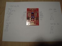
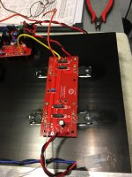
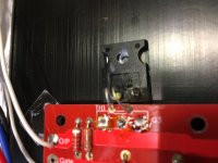
You used TIP31/32. They can be used instead of the TOSHIBA
2SC4793 (=TIP31) at Q7 and
2SA1837 (=TIP32) at Q8.
They have same pinout (all BCE). Orientation seems also correct.
How the TIP31/32 work in the F5T-circuit - I don't know. But they are cascode-transistors. They protect the JFets from too high voltage. Should work.
Greets
Dirk
Attachments
to luvrockin
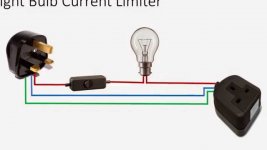
Luvrockin,
do you have a light-bulb-tester?
If not - make one. It is very easy to build/make and will 'rescue' your amp if anything is wrong.
The only difficulty today is to get a light bulb / filament bulb with around
100W (LED doesn't work!).
Dirk
Luvrockin,
do you have a light-bulb-tester?
If not - make one. It is very easy to build/make and will 'rescue' your amp if anything is wrong.
The only difficulty today is to get a light bulb / filament bulb with around
100W (LED doesn't work!).
Dirk
Attachments
to luvrockin
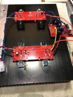
Please also check, that your thermistors (TH1 and TH2) on the outputboards are
in good contact to the Mosfet. It is good to glue them to the plastic-case of the Mosfet. Only one thermistor for the N-channel devices and only one thermistor for the P-channel devices.
Dirk
Please also check, that your thermistors (TH1 and TH2) on the outputboards are
in good contact to the Mosfet. It is good to glue them to the plastic-case of the Mosfet. Only one thermistor for the N-channel devices and only one thermistor for the P-channel devices.
Dirk
to luvrockin
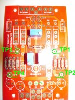
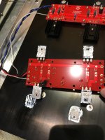
Now you check your resistance from TP1 to TP2 on the frontendboard.
If necessary, adjust Pot2 to get lowest possible resistance.
Remember which direction you turned the screw on trimpot to get resistance down. For biasing up (later) - other direction.
Do the same test (as described before) from TP3 to TP4 and adjust Pot1.
Dirk
Attachments
to luvrockin
O.k., luvrockin,
if you have checked all this - it is time to fire this 'baby' up!
From now on patience is your friend!!!
You decide which channel you want to bias up first (lets start with the right channel).
You will need minimum two ( better three) DMMs:
first DMM measures offset at speakeroutput. You set DMM to measure Volts (or mV). Red probe to speakerout + / black probe to speakerout -
second DMM measures bias (in mV) over one bias resistor at N - channel - board.
Red probe to TP2 / black probe to TP3 of outputboard (= bias N-channel).
third DMM measures bias (in mV) over one bias resistor at P - channel - board
Red probe to TP2 / black probe to TP3 of outputboard (= bias P-channel).
Now you put your dim-bulb tester between your amps AC-line and the AC-wall-outlet.
Take a deep breath!
Switch the amp on - the light bulb will light up bright and should dim down in brightness after 1-3 seconds.
If the light bulb stays on bright (after 2-3 seconds) - something is wrong - switch off!
If the light bulb is dimmed down - you should be o.k.. Check all 3 DMMs -
They should show values very close to 0 Volts.
Make the same test for the left channel.
These are all pre-checks before biasing up.
I hope nothing smells toasty!
Switch the amp off and let the PSU decharge (wait one to five minutes).
Put the dim - bulb - tester out and connect your amp directly to AC- walloutlet.
Now you are ready to bias one channel up. Follow the very good description in
post #2 of this thread.
I wish you success!
Good night!
Dirk
I replaced R5 & R6 with 2.2K resistors on the FE boards. Retested using the dim bulb tester, bulb dimmed to almost nothing, verified rail voltage was 51v (no load).
Waited a couple of minutes after disconnecting the dim bulb tester and turned on the power supply. All the meters read 0 mV except the rail which was 51vdc.
I started the bias adjustment of one FE board and the corresponding P & N channel output boards.
I was able to easily adjust 300 mV on the N channel and 280 mV on the P channel. The DC offset was moving from -6.7 mV to +1.2 mV, never very stable. always moving between these values. I put the lid and front cover on and waited about an hour.
Went back in using my Bourns, plastic adjusting tool, and dialed up the bias on the N channel to 330 mV, the P channel never would go above 300 mV. DC offset continued to vary between around -6 mV to + 2 mV.
P1 seemed to adjust bias, with P2 making small changes to the bias, I never went above 350mV until:
The adjusting tool slipped off of P2 while I was attempting to stabilize DC offset:
Then sparks, flames, smoke from the P channel and I shut everything down.
Attachments
More photos of burnt Q3 and lots of heat from D1 & D2 showing on heat sink.
After removing the FE and the N & P channel boards, I tested all the resistors, and they are all good, with in specs and no heat marks on any of them.
I don't understand how slipping off the pots while using a plastic tool could cause this.
I'm convinced that the DC offset being unstable had something to do with this. Not sure what to do except replace Q3, Q4 and D1, D2 just because of the heat.
Yet this channel had 10% less bias than the N channel.
Well, more data. On the FE board, P1 is stuck at 24.7 ohms measured between TP1 - TP2, no matter how many turns CW or CCW.
P2, when measured from TP3 - TP4, measures from 0.6 - 1.533K ohms. However, around the 300 - 400 range, the DVM blinks off and then back on, I tried this 10 times using two different DVM's with the same results.
After 48 years in the auto biz, this kind of result on a TPS would cause a hesitation with increase HC out the tail pipe.
I think P1 and P2 caused my event
to elwood625 #776
Hello Elwood,
I think you were running out of pot adjustment. Or the pot1 died.
You have +-51V rails? Perhaps you went too high with bias?
The dead Mosfet got very hot...
Did you bias up too fast? My experience with the F5-T is -
bias up slowly - not more than 10 - 20mV per step - let it get warmer (heatsinks)- wait 5- 10 minutes
readjust DC-offset (no more than 50mV offset) at speakeroutput - especially with that high railvoltage.
Also that thermistor looks suspicious - and the mark/sign on the Mosfet.
Isolation pads under Mosfets look o.k.. Possible short to heatsink???
But I can only assume?
I only can say - what a pitty!
Greets
Dirk
Guys, thank you all so much for the direction. I got hung up at work and just walked in. I will possibly attempt to check the items mentioned above. I just want to clarify, those cascode transistors Q7 & Q8 get very hot quickly, like in seconds. Is it ok to power up to get take the voltage readings or should I power on then let cool, then test again and so on?
Dirk, yes I do have a dim bulb tester. I made one the other day. I have a 300 watt bulb. Is that ok?
Dirk, yes I do have a dim bulb tester. I made one the other day. I have a 300 watt bulb. Is that ok?
- Home
- Amplifiers
- Pass Labs
- F5Turbo Illustrated Build Guide