Does anyone have the schematic and or service manual for the Threshold S/550? I was told that these amps normally came with a wiring diagram in their original owner's manual, but the manual for this one has disappeared a long time ago. This amp has high (1.5 volts) offset voltage on one channel while the other is fine. The amp does power up and everything, it is just that the one channel with the offset voltage issue is not working correctly.
I have this monster all apart. So far no bad output transistors. It powers up and rail voltages are even and look correct. Ditto for the feed to the two circuit boards. One channel is rock solid with a few milivolts of offset voltage. The other channel is another story. It works but sits there with about 1.5 volts of offset voltage. I'm thinking possibly that IC which is Q5 may be funky, or the bipolar differential pair Q3 and Q4. I don't really have a way of testing that IC, but voltages are not perfectly balanced in and around that circuit. I know that in the old Marantz 22xx Receivers I work on, if the differential pair is too far out of whack, the thing will not be stable and you are constantly tweaking that offset voltage pot. Anyway, it looks like an interesting project. At least it isn't as heavy to move around as the McIntosh stuff I am usually working on. Always a silver lining to every cloud!
Q3 and Q4 are merely cascodes, not likely to be the problem. Have you
identified that this is one or the other of the two front end schematics?
If there is an op amp for DC stability, check to see if its output is approaching
one of its rails, + or -. Note which, and also the polarity of the output offset.

identified that this is one or the other of the two front end schematics?
If there is an op amp for DC stability, check to see if its output is approaching
one of its rails, + or -. Note which, and also the polarity of the output offset.
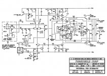
This amp has the front end with all the IC's. I'll make those checks you mentioned. I am assuming U2 is the opamp you are speaking of. It makes sense that if that IC was not sending out a balanced voltage to the gates of Q5, things would be a bit off at the speaker terminals.
I changed out the dual FET IC and the offset voltage dropped by a good 40%. But it is still over 1 volt. I have ordered some LM308's and plan to change that opamp out next. Voltages around the dual FET and that opamp are not perfectly balanced, but not that far off either. What is an acceptable DC offset voltage at the output terminals of these amps?
I have seen transistor power amps work fine with as much as half a volt of DC offset. Not desirable, but not fatal either. Where I see issues arise is when the things go much above half a volt.
Oh, what is the bias supposed to be on the S/550? Also, I stumbled across a model 400A and was wondering what the bias voltage should be for it. One channel had .138 volts across the .47 ohm resistors while the other channel had .035 volts across the same resistors in the output transistor circuit. The channel with .137 volts showed a heatsink temperature of around 120 degrees just sitting there with no signal while the other channel was running around 92 degrees on the heatsink. I'd like to get this guy biased properly. As is, it is working. I did drop the bias on the hot side to around .050 volt across the .47 ohm resistors. That channel now runs around 101 degrees with no signal, and warms up slightly when you start playing music through the amp. It sure is a nice sounding amplifier.
I checked the offset voltage and it went down a lot after replacing the NPD5566 dual FET chip. Went from a -2.1 volts to -1.3 volts. I replaced both M42 transistors and that LM308 opamp and it is now as -1.17 volts. If you flip that balanced to unbalanced switch on the back of the amp, the offset voltage will drop to - .92 volt in balanced mode then go up to -1.17 volt in unbalanced mode. Output transistors all tested good. This offset voltage issue is something I have seen in a lot of older complimentary and direct coupled transistor amps I have owned. It never seems easy to fix.
How critical are those 7 volts off the M42 transistors as well as that 7.5 volts across that zener diode? Should the 7 volts off each M42 be exactly the same ( like 6.8 volts for one and 6.8 volts for the other as opposed to something like 6.7 volts for one and 7.0 volts for the other)?
Just for testing purposes and to see certain voltages, (which are all but impossible to test with the board mounted on the heat sink assembly) can this board be removed and run by it's self on an external power supply so I can check for voltage problems at every component? Although changing what I did has made a marked improvement, the amp is still no where near where it should be with respect to offset voltage.
Hi,
I got both channels working properly. 17 uV offset voltage in the left channel and 11 uV in the right channel. ( was over 1 volt in one channel and over 2 volts in the other) What I found was that it was a combination of things. In both channels, replacing the Q5 chip (FEt differential pair) brought the offset voltage down by about 50% or so in both channels. But it was still too high. I then replaced the opamp U2 (LM308) and that brought the offset voltage in the left channel to 17 uV but the right was still too high. I found that the resistor R8 had a bad connection (because someone else had worked on this amp and not soldered the connection properly). Once that was fixed, the amp worked correctly. I did replace Q3 and Q4 in each channel and it dropped the offset voltage a few more uV to where it now is. I only have about 20 minutes playing time on it at present, but so far so good. I need to now find out how to bias this thing and what the setting should be. But for now, it runs cool enough and sounds quite nice. I am driving it with a similar vintage Threshold FET preamp. Very nice combination.
I got both channels working properly. 17 uV offset voltage in the left channel and 11 uV in the right channel. ( was over 1 volt in one channel and over 2 volts in the other) What I found was that it was a combination of things. In both channels, replacing the Q5 chip (FEt differential pair) brought the offset voltage down by about 50% or so in both channels. But it was still too high. I then replaced the opamp U2 (LM308) and that brought the offset voltage in the left channel to 17 uV but the right was still too high. I found that the resistor R8 had a bad connection (because someone else had worked on this amp and not soldered the connection properly). Once that was fixed, the amp worked correctly. I did replace Q3 and Q4 in each channel and it dropped the offset voltage a few more uV to where it now is. I only have about 20 minutes playing time on it at present, but so far so good. I need to now find out how to bias this thing and what the setting should be. But for now, it runs cool enough and sounds quite nice. I am driving it with a similar vintage Threshold FET preamp. Very nice combination.

The amp is running at 112 degrees f on one heatsink and 116 on the other. I have around 8 hours on it and so far so good. Sure is a nice sounding amp. I can try to upload pictures of it but I have had the worse time trying to get any of these sites to accept my uploads. Probably too big of a file.
I have this guy running with a Threshold preamp that belongs to another person I know. An FET ten I believe. The combination certainly does sound nice.
Powerful tight bass, nice smooth mids and very extended highs.. The first thing I noticed was the lack of ear fatigue experienced with this amp, even when cranked loud enough that you had to yell at a person next to you to be heard. I had the system hooked up with some cheap interconnects that I replaced with some DH Labs interconnects and speaker wire and that really helped open up the sound.. Anyone who says interconnects and speaker cables do not have an effect on a system's sound needs to try some higher quality ones like my DH Labs cables.
The build quality of this amp really is several cuts above anything else I have ever worked on, owned or used. My friend has an SA/4e that has been in his closet for about 5 years. Says one channel is giving issues. After hearing this guy, he is pulling that one out and wants me to go through it for him. I hear that the SA/4e works in class A and can double as a space heater. Should be interesting to compare the two if I can get the SA/4e running. What is wild is that the two amps look almost the same inside and the circuit boards are basically the same. From what I can see, the SA/4 uses a TO71 cased differential pair and the S550 uses a DIP 8 pin chip for the differential pair. Actually, they are both the same dual FET chips, just different form factors. Both use the LM308 to bias the FET's and the MPS42 transistors as a constant current source. The SA/4E was worked on by someone else who was never able to get it going. Of course, this S550 was worked on before as well and whoever worked on it could not get it going either. Man, I just love the look of these things. They just scream American made quality...My hat's off to Mr. Pass!
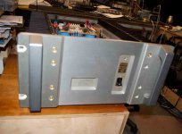
Ok, I'm going to try and upload a couple pictures of this amp. It has been playing happily in my shop for the past week and a half and sounds great. I want to thank you for all help getting this guy up and running again. This amp is a real work of art. Oh, my friend dropped off the S/A 4 so now I have another to fool around with. Cool.
Attachments
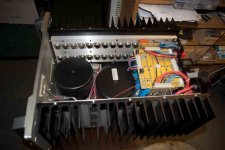
This may be an odd observation, but it looks like the S/A4 is the same amp as the S/550e, but with different biasing and rail voltages. The circuit boards are virtually identical with the exception that the differential pair IC for the S/A4 is a 6 pin TO71 case while for the S550e, it's a DIP 8 pin. Still, it's the same number and dual FET type. I only have the one channel working on the S/A4 (The other whole heatsink assembly is completely removed at the moment). Someone had tried their hand at fixing this guy unsuccessfully before. Anyway, I need to get this guy working since I'm really curious how this class A amp sounds. These amps are built so cool. A couple dozen phillips head screws and 8 allen screws and the whole thing comes apart. Nice. Man, those heatsink assemblies are heavy. Lot's of thermal mass there. Oh, I work on hifi gear as a hobby. Actually build some of my own amps and speakers. It all started because I was so sick of the crappy quality of most consumer electronics and because I just can not afford high quality amps like these Threshold amps. So I started picking up basket cases and fixing them. Also built my own tube amps because most were over priced and out of my financial reach. Now I also fix them for others since no one wants to work on these big amps around here. Must be something about an amp that is big enough to dim the lights when you use it that intimidates people.
Last edited:
Sweeet, fell in the love with look in the early 80's myself , always have one around the house. IMO its as Iconic as the mac look, nothing like the look of a pr of SA-1's ....
Even today ( sorry Nelson) ..
Yea, these amps are real masterpieces. Talk about an uncluttered sound. This S/550e is a joy to listen to. The amp produces virtually no ear fatigue. It is almost like a tube amp in that respect, but much more accurate sounding then most tube amps. The bass is amazingly tight. Run a square wave through it at low frequencies and it looks really good. At the high end, I don't notice that little spike at the lead edge of a square wave I see in most solid state amps and lesser quality tube amps. I wish I wasn't fixing these for other people that I know. Would love to own either the SA/4 or this S550e. It's funny. No one around where would work on these guys. Someone tried to fix the S/A4 but really made a mess of things. I have one channel working on that guy but they really butchered the circuit board for the other channel. Also, someone obviously slipped with a probe while testing because I can see the tell tale welding of a part of the power supply circuit board. Scary. Anyway, I'm going to give this other big Threshold the TLC it needs and deserves. Once I get these guys finished, I think I'm going to scare up the parts for one of those Burning Amps.. Probably a Burning Amp 2. I like Mr. Pass' amps and designs. Am so curious to hear one of those Burning Amps and I see one can order circuit boards for them.. That is if the person who owns this SA/4 doesn't sell it to me! One can only hope!!!
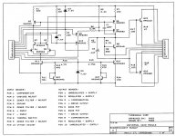
Where can I get a parts list for the transistors and other components shown on the schematics for these amps? I have the SA/4 apart and it looks like the two larger transistors that drive the stasis collector may be bad. I tried the numbers on the transistors and can not find them anywhere. the transistors have these numbers: 883 PSU60 and U10 749.
Look on the discrete schematic posted earlier, MPSU10 and 60.
Craig
Thanks Craig, I wasn't sure if that version of the front end for these amps used the same transistors as the one I have (which has the IC's and opto isolators). I'll see if I can find some of these...
- Status
- This old topic is closed. If you want to reopen this topic, contact a moderator using the "Report Post" button.
- Home
- Amplifiers
- Pass Labs
- Threshold S/550