I would consider the DC voltage under load and line variations. Conceivably
you may find the DC too close to the voltage of the zener stack.
Currently using a bench supply, but yeah good point!
So, I have 31.5V raw input and have 24V on the cases of the VFETs. I have proper bias voltages, 8.6V and -7.6V but no current following through the output stage (lab supply not going into constant current mode). Only difference from the schematic is I have 220 ohm in series with each gate, as preparing to parallel devices per my question above. I did lower R1 and related to 2K.
So, why no current fun? I hope the devices aren’t dead, but I haven’t killed any yet... I am not sure where to check!
Last edited:
I see. My voltages don’t seem to go low enough. The article recommends 4 to 12v range. I seem to only be able to get to 6.5V which is .54A through the output stage. Hm.
Seems like 4V isn’t possible with the values given in the circuit. If we move to a 3K resistor with a 5K pot, I think we can get 2.5(1+3K/5K) = 4V.
Maybe I have the bottom of the barrel vFETs
")
You should be prepared for the possibility of 12V.
These are the absolute bottom of the batch I have. I see why you changed some of the parts when you knew what the devices going to the DIYA shop were going to be
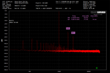
Pretty good performance, this one using Cinemag input transformers and no buffer. I have fixed my relay arrangement so I can swap it in - just need to partially case it so I can play and test this out.
Fun stuff!

These are the absolute bottom of the batch I have. I see why you changed some of the parts when you knew what the devices going to the DIYA shop were going to be
No, the performance of the 12V parts is fine, but you have to make an
allowance for those values.
The new design reflects the very limited quantity of parts, not the quality.
I can offer about 400 channels instead of 200 and it also is a different
approach, having a different sound.
Pass DIY Addict
Joined 2000
Paid Member
Here are some pictures of my dual CSX2/VFET2 capable amplifier. Single output stage that can be built for either amplifier, and two different input boards.
Need to get my buffers finished up to pop in there and will do some comparison measurements.
Rails are +/- 30V and biased to 1.5A. Buffers get +/- 23V. The VFETs are installed into pin sockets, so don’t require soldering or lead trimming. I can just add a few more and the rebias, up to 3 pair per side.
Hopefully will have time over the holidays to get the CSX2 variant measured!
I think I have a ground loop. On the scope it looks like a squiggle near zero volts and when looking at frequency response graph I get strong 60Hz with harmonics. I can post graphs if it’s helpful.
I am assuming pin one on the XLR goes to chassis which is connected to IEC earth, with standard half-bridge and thermistor connecting to ground. The shell of the XLR connector also goes to chassis (earth). Then the input buffer grounds are connected to PSU ground with of course is the output ground.
I will do some poking around, but I think all the above is true.


OK, May seem a strange question, but where is the schematic to match the CSX1 Sony VFET PCB board that was sold a few years ago? The Pass article shows a schematic that is sort of like it...but it is NOT the same. Also, the RCA single ended input goes to XLR- and gnd - should this not be XLR+ and GND? As the XLR- then is shorted to GND to use single-ended? How many out there actually built this amp?
Permaneder R.I.P. made boards for this project. The circuit is so elastic for make many changes, paralleling the input, balanced or SE. I have two boards yet, still not populated. WALTER Diy member finished this amp early and he is to happy. Jama did finish the circuit and was satisfy but right now he return to valve world. I am still finishing this amp paralleling the Vfet. There are not NF and probably the damping is low. But in biamp or with high sensitivity speakers such lowther or AER or Feastrex is a cute low distortion natural sound amp with an incredible Wideband. I got identical matched quad, the 28s have the same curves envelope that the 82s's. Permaneder include all the component in the board and make a good solution for use any cabinet.
- Status
- This old topic is closed. If you want to reopen this topic, contact a moderator using the "Report Post" button.
- Home
- Amplifiers
- Pass Labs
- Article - Sony VFETs part 1