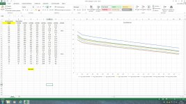
Today I measured my VFET's the 2SJ28 KE-33 @24V, and these are the results.
I will do the same for the 2SK's.
The one in my CSX1 with the strange, high bias voltage is the VFET#8, and it is almost the same as VFET#4. The voltages are higher but the curve and slope looks good.
Are they useful in the CSX1, or should I replace with another one?
I will do the same for the 2SK's.
The one in my CSX1 with the strange, high bias voltage is the VFET#8, and it is almost the same as VFET#4. The voltages are higher but the curve and slope looks good.
Are they useful in the CSX1, or should I replace with another one?
Attachments
Infrared Thermometer trick for measuring shiny surfaces
Walter,
Very nice job on your amp!
A trick to use to get your infrared thermometer to measure shiny surfaces is to put a piece of masking tape on the device. The tape will be at very close to the same temp as the device being measured and isn't shiny so you can get a reading. ;-)
Again, great job so far!
Steve
Hello Steve. Additional thoughts came to mind after reading your post. A patch from a black Sharpie, or another made with a dark nail polish.Walter,
Very nice job on your amp!
A trick to use to get your infrared thermometer to measure shiny surfaces is to put a piece of masking tape on the device. The tape will be at very close to the same temp as the device being measured and isn't shiny so you can get a reading. ;-)
Again, great job so far!
Steve
Best regards.
... do you think it will work .......
yup
YEp
Thats true love...") Great I miss him tooo...
Great I miss him tooo...
I miss Sound Happy. Where is he?
Best regards.
Thats true love...
Great I miss him tooo...Walter,
Very nice job on your amp!
A trick to use to get your infrared thermometer to measure shiny surfaces is to put a piece of masking tape on the device. The tape will be at very close to the same temp as the device being measured and isn't shiny so you can get a reading. ;-)
Again, great job so far!
Steve
Thanks for the trick !
They get around 75C at the top where the text is.....
Acceptable for a TO-3?
Jama is calling every day and saying every day sound better.
At the moment nothing at home but waiting for the final GB at US.
I am asking to Walter, How sound at this Tº? Does become more hot with loud passages? Or is stable?
I still miss to sound, cx1 and Happy.
Best regards
At the moment nothing at home but waiting for the final GB at US.
I am asking to Walter, How sound at this Tº? Does become more hot with loud passages? Or is stable?
I still miss to sound, cx1 and Happy.
Best regards
Jama is calling every day and saying every day sound better.
At the moment nothing at home but waiting for the final GB at US.
I am asking to Walter, How sound at this Tº? Does become more hot with loud passages? Or is stable?
I still miss to sound, cx1 and Happy.
Best regards
It sounds fine at 75C
But It's class A so when I play it loud it should become less hot.I'm experimenting with different TO3 heat conducting foil, and the Kerafol 70/50 isn't the best, when the TO3 case is 75C, the L shaped sink is 58C....
With 0.1mm mica and grease I get around 8-10C difference, same as with self cut Kerafol 80/20.
So as Papa says : use mica and grease
BTW: is papa saying I can get to 100C at my TO3 case?
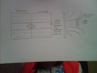
You have SK88, but connected with 5mm L aluminium one transistor for two heatsinks
You can put two sinks SK88 together, united by a transistor, so the transistor stay with one half in each. Furthermore interposing a copper plate 30mm wide by 5mm thick all along the two sinks (200m) this will improve the transfer of heat from the transistor to the plate and is about to be copper and bigger, will transfer faster and homogeneously temperature. The only drawback of this method is that you must completely change the mechanical structure of the amplifier.
You can put two sinks SK88 together, united by a transistor, so the transistor stay with one half in each. Furthermore interposing a copper plate 30mm wide by 5mm thick all along the two sinks (200m) this will improve the transfer of heat from the transistor to the plate and is about to be copper and bigger, will transfer faster and homogeneously temperature. The only drawback of this method is that you must completely change the mechanical structure of the amplifier.
Attachments
The juncture Tº is 150ºC. Anyway the SK88 is recommended for TO3 but you not uses the normal way for the design of the design and actually the SK88 is one of the cheapest practical professional and handsome. Maybe you could make one amp with two Vfet for side spreading in the same number of heathsinks but with better transference, the other that you can do is putting the wings from to inside and put a fan inside from button to up.
Best Regards
Best Regards
Haha, Esteban, I know it's not the normal way of using a SK88
It looks nice this way and I like doing things a bit different. I could get the SK88s pretty cheap in Amsterdam at a kind of dump store, so I could do a quick build.
If I like the amps I build them on some bigger heatsinks for sure, I ordered some nice PCB's from the group buy also.
It's difficult listening to the left channel a CSX1 and the right channel a ACA
I can tell you it sounds different, the ACA ( with the IRFP240s) is a bit sharp at the highs and mid highs compared to the CSX1. Again it's hard too listen to two different amps.
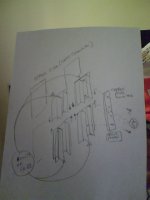
Four SK88 for side and...
One channel per side. Imagine in the pic there are two units bound for one 3mmX30mmX200mm copper plate, with a kheratec between the Vfet and the copper plate This plates are common here on Europe like standard in construction of electrical distributors. They are really cheap.
RS sales SK88 in 8 € each. They are SK88 in 1000mm long, for industrial sales, is good because you can cut the size you need. Getting one of them you have enough for a 0,4 K/W with 20cm long. I tried in get here on europe but finally I can't.
Attachments
150mW too much for 2sk170/2sj74?
I am just testing out the front end to my CSX1 and I need to know whether 150mW is too much dissipation for one channel of my 2sk170 and 2sj74 buffer?
I did have some BL grade in both channels, but after a small accident when wiring up I had to replace one channel and only had a pair of V grade to replace them with...
I know the max dissipation is 400mW on the datasheet for both devices, but am I pushing it with 150mW for each in free air?
Should I try to slip a small heatsink on them or replace with some new BL grade?
Thanks, ianc13
I am just testing out the front end to my CSX1 and I need to know whether 150mW is too much dissipation for one channel of my 2sk170 and 2sj74 buffer?
I did have some BL grade in both channels, but after a small accident when wiring up
I had to replace one channel and only had a pair of V grade to replace them with...I know the max dissipation is 400mW on the datasheet for both devices, but am I pushing it with 150mW for each in free air?
Should I try to slip a small heatsink on them or replace with some new BL grade?
Thanks, ianc13
- Status
- This old topic is closed. If you want to reopen this topic, contact a moderator using the "Report Post" button.
- Home
- Amplifiers
- Pass Labs
- Article - Sony VFETs part 1