I had successfully build an Aleph 2 and now I want to go to a next step ahead changing the front-end to Jfet (2SJ74/LSJ74) building a small daughterboard that connect to IRF9610 diff pair mounting holes. My knowledge of electronics is very limited, I try to find something similar but only found Aleph-J or Aleph-X references that have a considerable lower rail voltage, so I’m asking for help.
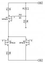
The first thumbnail image represents the actual IRF9160 diff pair (simplified) on the Aleph 2 circuit.
There are two published approach that I found that are near to the requirements, but they are for a lower rail voltage, the first is from Eric's Aleph-X construction notes, the complete article section can be found on Aleph-X 100w Amplifier Construction Notes, and a sample diagram of JFet replacement at http://www.facstaff.bucknell.edu/esantane/movies/JFET-input.jpg. The second one is from Graeme published on diyaudio thread http://www.diyaudio.com/forums/pass-labs/73543-ax100-100w-aleph-x-monoblocks-46.html#post1468122.
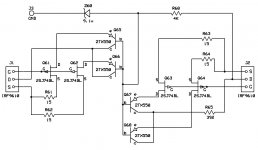
I have read many posts on diyaudio and other places about people asking for Jfet front-end for Alephs, but I didn’t find a finished schema, so I made my own, please see second thumbnail image.
First all, J1 and J2 represent the actual IRF9610 (Q1 & Q2) on the board and J3 will be a direct connection to the star-ground point. The drain pin of Q2 on Aleph 2 schema is directly connected to negative rail, so I can take from here the -45. I choose to use the Toshiba 2SJ74BL because the 2SJ109BL are really impossible to get from a trusted source, and also the 2SJ74BL could be find matched quads. R61 to R64 are the Jfet source resistors that Graeme used is his schema. R65 represent a drain resistor to negative rail for Q2 like Graeme used on the AX100J and also Nelson Pass recommend on his following post http://www.diyaudio.com/forums/pass-labs/146767-j-fet-front-aleph-5-a.html#post1869842.
Questions:
- How the schema looks like, I’m crazy or it’s possible to do that?
- The values of R61 to R64 (15R) are ok for Aleph 2?
- The 2SJ74 Q61-Q62 and Q63-Q64 will require some type of heatsink, also they should be thermally coupled?
Any comment will be appreciated, thanks in advance.")
The first thumbnail image represents the actual IRF9160 diff pair (simplified) on the Aleph 2 circuit.
There are two published approach that I found that are near to the requirements, but they are for a lower rail voltage, the first is from Eric's Aleph-X construction notes, the complete article section can be found on Aleph-X 100w Amplifier Construction Notes, and a sample diagram of JFet replacement at http://www.facstaff.bucknell.edu/esantane/movies/JFET-input.jpg. The second one is from Graeme published on diyaudio thread http://www.diyaudio.com/forums/pass-labs/73543-ax100-100w-aleph-x-monoblocks-46.html#post1468122.
I have read many posts on diyaudio and other places about people asking for Jfet front-end for Alephs, but I didn’t find a finished schema, so I made my own, please see second thumbnail image.
First all, J1 and J2 represent the actual IRF9610 (Q1 & Q2) on the board and J3 will be a direct connection to the star-ground point. The drain pin of Q2 on Aleph 2 schema is directly connected to negative rail, so I can take from here the -45. I choose to use the Toshiba 2SJ74BL because the 2SJ109BL are really impossible to get from a trusted source, and also the 2SJ74BL could be find matched quads. R61 to R64 are the Jfet source resistors that Graeme used is his schema. R65 represent a drain resistor to negative rail for Q2 like Graeme used on the AX100J and also Nelson Pass recommend on his following post http://www.diyaudio.com/forums/pass-labs/146767-j-fet-front-aleph-5-a.html#post1869842.
Questions:
- How the schema looks like, I’m crazy or it’s possible to do that?
- The values of R61 to R64 (15R) are ok for Aleph 2?
- The 2SJ74 Q61-Q62 and Q63-Q64 will require some type of heatsink, also they should be thermally coupled?
Any comment will be appreciated, thanks in advance.
Attachments
The Mighty Zen Mod has written a note on changing the Aleph front end to
Jfets:
http://www.diyaudio.com/forums/pass-labs/75281-babbelfish-j-pcbs-38.html#post1112763
Hope this helps.
Dennis
Jfets:
http://www.diyaudio.com/forums/pass-labs/75281-babbelfish-j-pcbs-38.html#post1112763
Hope this helps.
Dennis
Which configuration recommend to try?
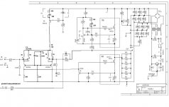
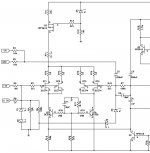
I've done my homework, at least up to my limited knowledge allow. I got 3 different configurations that may work, can someone review the images and let know what think about?
Thanks again to all that share their valuable knowledge and experience.
Regards,
Alejandro
I've done my homework, at least up to my limited knowledge allow. I got 3 different configurations that may work, can someone review the images and let know what think about?
Thanks again to all that share their valuable knowledge and experience.
Regards,
Alejandro
Attachments
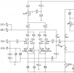
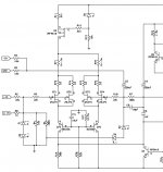
most left one
you can make R71 and R72 as just one
Thanks for your reply, I will start collecting the parts to build a proto-board of the left schema.
I split the resistor in R71 & R72, because it will simplifly to me the final design of the daughterboard.
Regards,
Alejandro
Yes the left one but stick some resistors in the base leg of cascodes 220 Ohms - 1K.
Thanks for the tip, as I could understand I will make a new schema with a pair of resistors in between the base legs of Q75 & Q76.
What value should I use for those resistors? 220Ω - 1KΩ is a wide range.
Regards,
Alejandro
I would strongly recommend matching all the JFETs in each channel as closely as possible.
I only used the 15 ohm source degeneration resistors in the AX100J because that was the value I had on hand. I also tried no resistors and that worked fine too - but the JFETs were all tightly matched.
I think your Aleph 2J is going to sound really, really nice!
Graeme
I only used the 15 ohm source degeneration resistors in the AX100J because that was the value I had on hand. I also tried no resistors and that worked fine too - but the JFETs were all tightly matched.
I think your Aleph 2J is going to sound really, really nice!
Graeme
I would love to try this - i've just been looking at my long dormant Aleph 2s, to re-do the wiring and fix a few things.
A chance to refresh them with a new front end would really rock!
I wish i could do more than just offer moral support, but it's over my head technically
A chance to refresh them with a new front end would really rock!
I wish i could do more than just offer moral support, but it's over my head technically
I would strongly recommend matching all the JFETs in each channel as closely as possible.
I only used the 15 ohm source degeneration resistors in the AX100J because that was the value I had on hand. I also tried no resistors and that worked fine too - but the JFETs were all tightly matched.
I think your Aleph 2J is going to sound really, really nice!
Graeme
Thank you for your advice, fortunately today is still possible to buy the Toshiba 2SJ74BL in matched quads. I have some LSJ74 but I haven't luck with match, I will need to continue buying more units to get a good matched subset.
Best regards,
Alejandro
C71 - 10uF/25V electrolytic is fine
OK thanks, I need to change the symbol in the schema, I was thinking in a non polarized capacitor.
Thanks,
Alejandro
Daughterboard design finished
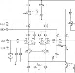
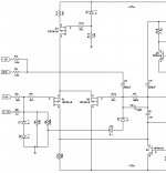
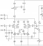
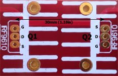
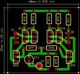
I have finished the Aleph 2 Jfet daughterboard design (I hope), there are 4 attached images, from left to right, (1) original Aleph 2 input stage, (2) the revised Aleph 2 Jfet input stage, (3) the actual mainboard IRF9610 diff pair and (4) the Jfet daughterboard PCB.
J1 & J2 are the connections from daughterboard to Q1 & Q2 (IRF9610s) on the main Aleph 2 board respectively, the orientation of pins is exactly as they are on the mainboard. Also the distance between Q1 & Q2 is the same as in between J1 & J2 (30mm or 1.18in), the idea is to directly plug the daughterboard into Q1 & Q2 pin connections.
An important fact is that drain pin of Q2 (center pin) is directly connected to negative rail, another fact is “source” pin of both Q1 & Q2 are already direct connected at the mainboard level as the original design states, as a way of simplify daughterboard design only the “source” pin of Q2 was used.
The rest is in the previous posts.
I have changed some resistors designations in the schema because there was a repeated number.
If anyone has time to see the diagrams and the PCB, and post any comment I will be very gratefully.
Thanks in advance.
Alejandro
I have finished the Aleph 2 Jfet daughterboard design (I hope
), there are 4 attached images, from left to right, (1) original Aleph 2 input stage, (2) the revised Aleph 2 Jfet input stage, (3) the actual mainboard IRF9610 diff pair and (4) the Jfet daughterboard PCB.J1 & J2 are the connections from daughterboard to Q1 & Q2 (IRF9610s) on the main Aleph 2 board respectively, the orientation of pins is exactly as they are on the mainboard. Also the distance between Q1 & Q2 is the same as in between J1 & J2 (30mm or 1.18in), the idea is to directly plug the daughterboard into Q1 & Q2 pin connections.
An important fact is that drain pin of Q2 (center pin) is directly connected to negative rail, another fact is “source” pin of both Q1 & Q2 are already direct connected at the mainboard level as the original design states, as a way of simplify daughterboard design only the “source” pin of Q2 was used.
The rest is in the previous posts.
I have changed some resistors designations in the schema because there was a repeated number.
If anyone has time to see the diagrams and the PCB, and post any comment I will be very gratefully.
Thanks in advance.
Alejandro
Attachments
- Status
- This old topic is closed. If you want to reopen this topic, contact a moderator using the "Report Post" button.
- Home
- Amplifiers
- Pass Labs
- Help wanted: Jfet front-end for Aleph 2