This expired patent is entitled "Active Low Frequency Acoustic Resonance Suppressor". It was granted on Feb. 6 1990 to Threshold Corporation; Nelson S. Pass inventor. His inventive device eliminates standing waves [SW] in rectangular music listenning rooms. Thus it enhances the accuracy, perception and enjoyment of music etc...IMHO, this device is a must tool for DIYaudiophiles. For a couple of years, I've had 2 diy stereo resonators, and have recently prototyped a third mono device [for this thread]; all in my rectangular music room.
I hope that Mr. Pass has no objections, and there is interest in diy'ing [his approach] to solve this fundamental and pervasive problem. I'll wait a week before I move forward.
Best regards.
I hope that Mr. Pass has no objections, and there is interest in diy'ing [his approach] to solve this fundamental and pervasive problem. I'll wait a week before I move forward.
Best regards.
Have a look at patent 6,795,557 which cites 4,899,387 as prior art.
This might be nothing but salesmanship, suggesting to the patent examiner that all previous approaches are flawed, whereas my new invention glows with burnished perfection.
2. Description of the Related Art
In U.S. Pat. No. 4,899,387 is further disclosed an apparatus for cancelling low-frequency acoustic resonances in a room used as an acoustic space. The apparatus is particularly suited for improving room acoustics in listening to music. The major single factor causing acoustic frequency response variations typically is the listening room itself that may readily cause deviations as large as 20 dB at some frequency in the amplitude response in a given point of the listening room. These deviations are caused by the interference of sonic pressure waves reflecting from the walls of the listening room with pressure waves radiated directly from the loudspeakers. Obviously, the need for improved listening room acoustics is urgent.
The embodiment described in cited U.S. Pat. No. 4,899,387 attempts to solve the above-described problem by placing cancellation apparatus units in the room at the pressure maxima or in the immediate vicinity thereof. Said cancellation apparatuses comprise a microphone for sensing the sound pressure waves and signal processing means and a cancelling loudspeaker for producing the cancelling pressure waves to the reflected original sound thus measured. In this arrangement, the microphone is located close to the cancelling loudspeaker, and with the help of a feedback circuit, the goal is to alter the acoustic impedance of the cancelling loudspeaker such that the effect of the room acoustics on the smoothness of the sound field is eliminated. This technique bears the risk of instability of the feedback loop that also includes the sound cancellation apparatus itself, whereby the system may start to oscillate.
This might be nothing but salesmanship, suggesting to the patent examiner that all previous approaches are flawed, whereas my new invention glows with burnished perfection.
Thank you Mr.Pass.I have been thinking about resurrecting that myself.
Have at it.

Have a look at patent 6,795,557 which cites 4,899,387 as prior art.
This might be nothing but salesmanship, suggesting to the patent examiner that all previous approaches are flawed, whereas my new invention glows with burnished perfection.
Thank you Mark Johnson for this heads-up US Patent# 6,795,557. I looked at its diagrams, and was dismayed as they appeared complex to me; unlike US 4,899,556 which is way simpler, elegant, and highly effective.
Acoustic Absorber
This diy is a tribute to Mr. Pass, his genius, and a gift to us who are in constant pursuit of the most pleasing and accurate musical experience.
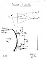
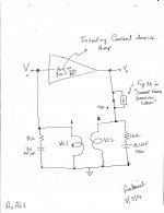
The attendant schematic shows the two building blocks which makeup the Acoustic Absorber [AcAb].
This diy is a tribute to Mr. Pass, his genius, and a gift to us who are in constant pursuit of the most pleasing and accurate musical experience.
The attendant schematic shows the two building blocks which makeup the Acoustic Absorber [AcAb].
- A current source amplifier. A diyF6 is used initially as a teaching aid since most of us are familiar with it.
- A dual voice coil subwoofer, used as a combination microphone and loudspeaker. This approach is totally within the inventive scope of the Pass patent.
- Acoustic pressure [Pa where a is for action] pushes the cone in.
- Voice Coil 1 [VC1] acts a a moving coil microphone. Thus, it generates an electrical signal which is [Vi] to the input of the amp. Note its phase. The analogous electrical signal in VC2 due to the same [Pa] is irrelevant and is ignored.
- Vi is amplified and the output of the amp [Vo] is impressed on the second voice coil VC2. Note the phase of Vo in relation to the "phase symbol" of VC2 [bold triangle].
- The loudspeaker magnet-VC2 "motor" combo then generates an instantaneous reactive force [Pr where r is for reaction] which pushes the same cone outward; in effect opposing or counteracting the action of the incoming [and offending] pressure wave [Pa].
Attachments
Hello soundhappy. I'll stay with this style of schematics.Hi Antoinel
You are Pablo Picasso of quick schematic !
I like hand drafted with signature my good luck to You.
Keep that diy style please
Greetings
Best regards
Acoustic pressure [Pa where a is for action] pushes the cone in.
...
The loudspeaker magnet-VC2 "motor" combo then generates an instantaneous reactive force [Pr where r is for reaction] which pushes the same cone outward; in effect opposing or counteracting the action of the incoming [and offending] pressure wave.
I think you have this reversed. Pressure which pushes the cone in, met with
forces which push the cone out, will result in greater pressure.
We want zero pressure, practically speaking, reduced pressure.
I don't think you need to do this instantaneously, as is being proposed here. The standing waves can be determined based on room dimensions and the source (i.e., loudspeaker) locations in the room. Once you determine the variations at the listening position, you can apply EQ to your sources, or you can place more sources, as in the patent, around the room to cancel the effect of the standing waves. In fact, I am running my system this way.
You need DSP (miniDSP), multiple amps and subs, and measurement programs, such as REW. REW will even generate the EQ for you. It has a superb room modeling module as well.
You need DSP (miniDSP), multiple amps and subs, and measurement programs, such as REW. REW will even generate the EQ for you. It has a superb room modeling module as well.
Thank you for the correction. I made the mistake of equating Air Pressure [Force per unit area] with Force. There are 3 possible outcomes from AcAb:I think you have this reversed. Pressure which pushes the cone in, met with
forces which push the cone out, will result in greater pressure.
We want zero pressure, practically speaking, reduced pressure.
- The cone does not move at all [i.e. locked] when the external and internal Forces acting on it are equal. Get an ideal zero Air Pressure at the cone's surface. The offending standing wave is no more.
- The impinging external force somehow exceeds the reactive internal force. Get a diminished air pressure at the cone's surface. This standing wave is partially wiped out.
- The internal force somehow exceeds the external force. Get a phase inverted outgoing wave. As if the original wave is reflected, and the loudspeaker now behaves as a normal subwoofer.
Thank you ra7 for your comments. You have a sophisticated system , and I admire your ability to understand and manage it. Way above my abilities; but I hope to understand too. Maybe in the future you may consider comparing the Pass approach with your current system; as you already have amps and subs.I don't think you need to do this instantaneously, as is being proposed here. The standing waves can be determined based on room dimensions and the source (i.e., loudspeaker) locations in the room. Once you determine the variations at the listening position, you can apply EQ to your sources, or you can place more sources, as in the patent, around the room to cancel the effect of the standing waves. In fact, I am running my system this way.
You need DSP (miniDSP), multiple amps and subs, and measurement programs, such as REW. REW will even generate the EQ for you. It has a superb room modeling module as well.
Best regards.
Antionel, this can't be right ?
"The cone does not move at all [i.e. locked] when the external and internal Forces acting on it are equal. Get an ideal zero Air Pressure at the cone's surface. The offending standing wave is no more."
If the cone is in fact locked all that would happen is that the waves get reflected back into the room ? So a few bricks could have the same effect ?
Maybe the cone needs to move inwards to create rarefaction instead?
Interesting investigation btw, thanks...
Antionel, this can't be right ?
"The cone does not move at all [i.e. locked] when the external and internal Forces acting on it are equal. Get an ideal zero Air Pressure at the cone's surface. The offending standing wave is no more."
If the cone is in fact locked all that would happen is that the waves get reflected back into the room ? So a few bricks could have the same effect ?
Maybe the cone needs to move inwards to create rarefaction instead?
Interesting investigation btw, thanks...
Hello kasey197. Great to hear from you. Thank you for your comments. The undetlined in your post got me thinking of this example which I hope may clarify your question. Envision two athletes who are arm wrestling. Their arms are upright,they grimace, pant,etc... But are they faking this duel [zero force exchange], or are they truly competing. Either way, their arms appear or actually are motionlessr to a spectator. Either way, athlete1 moves its arm one degree of vertical to the right while athlete2 senses this motion of athlete1, and reacts with a force to restore the original status quo; be it faking or competing. Also, It seems to me that I am explaining [to myself] the mechanism of a DC servo and/or loop feedback, and/or my understanding of Le Chatelier's Princinple.
Best regards
Last edited:
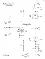
Amplifier schematic of Acoustic Absorber
I am glad to say that I see in it contributions from Mr. Pass, Zen Mod, lhquam, buzzforb, generg, Tea-Bag and all of you who posted in the diyF6 Amp thread. Note the following:
Best regards
I am glad to say that I see in it contributions from Mr. Pass, Zen Mod, lhquam, buzzforb, generg, Tea-Bag and all of you who posted in the diyF6 Amp thread. Note the following:
- The amp inverts the phase of input signal [Vi].
- It is a current source amp prior to loop feedback which is mediated by the subwoofer driver.
- This particular negative feedback can be called "Transformer-Coupled Schade and/or Pass". A similar name maybe "Electromagnetically-Coupled ...."
- The dual coil subwoofer driver is written as a 1:1 transformer. Note the phase symbols on it.
- As shown, the amp is stable or silent. But it oscillates when the connection of VC1 or VC2 is reversed; due to Schade and/or Pass positive feedback.
- Four versions of the subwoofer exist; with and without a passive low pass filter ahead of the voice coils.
- Vo centers at ~0 V with a trivial DC offset of <50 mV.
- Each voltage regulator chip operates like a depletion device. Idle current is ~300 mA through each.
Best regards
Attachments
Last edited:
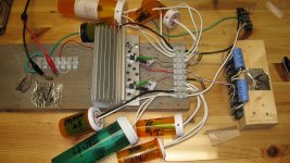
Prototype AcAb Amplifier
The picture of the prototype AcAb amp is shown. Nothing fancy. I will continue to use it to generate data. Note the following:
The picture of the prototype AcAb amp is shown. Nothing fancy. I will continue to use it to generate data. Note the following:
- The tubes are plastic pill containers. Two identical sets are shown flanking the heatsink.
- Each set has a container for a 10,000 uF/50V cap, for a 4 Ohm/40W non-inductive resistor, for a 1 Ohm/5W and wirewound resistor, and for 1/2 Ohm/5W and ww resistor. The ww resistors are connected in paralell to give 0.33 Ohms as shown in the schematic of the previous post.
- The tube housings protect against shorts.
- The + and - 15 VDC regulated PSU is not shown.
- The input [Vi] for voice coil 1 is the centerpoint of the 1,000 uF capacitor as shown on the far right of the picture sitting atop a small block of wood.
- The output [Vo] to voice coil 2 is shown on the far left side of the picture.
- The heatsink gets lukewarm with the chips dissipating ~9 W.
Attachments
A dual coil subwoofer for the Acoustic Absorber
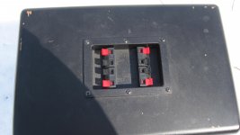
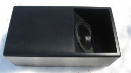
I bought a pair of the pictured subwoofer from MCM Electronics a while ago. The white background under the loudspeaker is snow. This subwoofer was designed to sit in the corner in a floor or a wall joist. In the second photo, I show its [speaker] connectors to the power amp. Immediately beneath them is a dual crossover; with individual outputs to R and L satellite speakers. I bypassed both crossovers for this study. But I have the twin of this subwoofer with its crossovers in place for a comparison of perfomance to be done in the future.
Best regards
Attachments
Moving forward
Hello everyone. The voltage gain of the current source amp driving an 8 Ohm non-inductive power resistor is [Av = 40 at 100 Hz.]. Divide this result by the value of the load [8 Ohm] to get a transconductance; Gm = 5 Amps out per unit input Vi.
The attached pictures declare these important observations.
used to test the operation anof the Acoustic Absorber.
Best regards.
Hello everyone. The voltage gain of the current source amp driving an 8 Ohm non-inductive power resistor is [Av = 40 at 100 Hz.]. Divide this result by the value of the load [8 Ohm] to get a transconductance; Gm = 5 Amps out per unit input Vi.
The attached pictures declare these important observations.
- The impedance of each voice coil is 8 Ohms.
- I disabled the commercial crossover network which came with the subwoofer.
- Must have a Zobel across VC1 to prevent oscillation of the assembly. Its purpose is to neutalize the rising impedance of "inductance" with increasing frequency. This Zobel [not optimized] is an 8 Ohm non inductive resistore in series with a 70uF NP electrolytic.
- The Zobel across VC2 is less important than that across VC1. It is the classical 10 ohms in series with a 0.1uF film cap seen in commercial amps. Its presence sharpens the low frequency noise trace seen on the scope, and/or gets rid of blur riding on it.
- There is room for a Low Pass filter in series with VC2. This is like that shown and taught in Fig. 3A of the article by Mr. Pass which is entitled "Current Source Crossover Filters"
Best regards.
Attachments
- Home
- Amplifiers
- Pass Labs
- DIY the device of US Patent 4,899,387