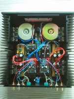
Hi. I have build a pair of Aleps 5's based on the PCB's from Chipamp.com. I have build the amps as close as possible to the Aleph 5 service manual. The PSU is build as dual mono.
The amp is working but for some reason the current is not the same in the two channels. One draws 1.75 A and the other only 1.35 A. I was expecting the boards to draw something like 2 A per side, so I find this to be a little odd. I am 95 % certain that the values of the components on the 2 boards are the same and I have used matched transistors. I don't really know where to start the debugging. Can anybody point me in the right direction?
Thank you
Mikkel
PS. I have tried to upload a components list, if that helps any.
Attachments
I'm guessing without the schematic, but in the ACS, check the value of R10, (68K) lower values decrease bias. Also check the voltage across R18 - are you getting ~4.5V? If this is low, you'll need to adjust the value of the resistor in the front end current source to increase front end bias.
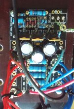
A copy of the schematic with measured voltages annotated would be helpful for troubleshooting. As would in focus close ups of your boards.
A copy of the schematic with measured voltages annotated would be helpful for troubleshooting. As would in focus close ups of your boards.
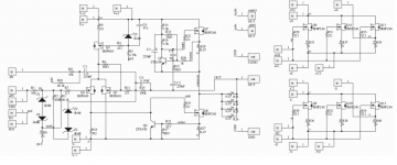
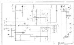
You need to annotate diagram 2 with the voltages that you are actually experiencing. The differences that you are seeing may only be down to component tolerances.
As long as both channels are being biased into Class A I doubt whether you will hear any audible difference.
I've got the Aleph 4 which uses the same topology, have you measured the voltage across each source resistor? You need to to check your component matching and to ensure current sharing. When mine was built I'm sure the matching was pretty well spot on. All the MOS-FETs in Channel A need to be matched as do those in Channel B, but Channel A doesn't need to be matched to Channel B. The CCS doesn't need to be matched to the amplifying set either so you will see a mismatch unless all the MOS-FETs are matched which is unnecessary.
Last edited:
Since we are looking to verify output stage function and matching, annotating measured voltages across R35-40 on that on the first picture would help, too.
On your board, what are the voltages across R18? What value did you choose for R13? Do they match? That's the one that adjusts ACS current. Higher is more bias.
On your board, what are the voltages across R18? What value did you choose for R13? Do they match? That's the one that adjusts ACS current. Higher is more bias.
I'll note some measured values as soon as I get a chance.
About the sound. It sounds great. It was only because I made some control measurements that I notised the problem.
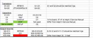
About mosfet matching. The 3 mosfets on each output board are matched in pairs of 3.
I have attached some pics of the amp and main board
About the sound. It sounds great. It was only because I made some control measurements that I notised the problem.
About mosfet matching. The 3 mosfets on each output board are matched in pairs of 3.
I have attached some pics of the amp and main board
Attachments
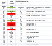
Here are some values:
voltage across the sourcs resisters (1ohm) on the output board:
Resistor Right ch Left ch
35 0,55V 0,58V
37 0,57V 0,34V
39 0,58V 0,34V
36 0,59V 0,42V
38 0,56V 0,42V
40 0,56V 0,43V
Maybe there is a problem with the matching of Q9,11 and 13? Maybe R37 and 39 are of. I dont remember the tolerance for these (5%?). I got them from ebay.
I also measured the voltage over R18 : 4,8V (R-ch) and 4,6V (L-ch)
The DS voltage across Q5: 4,77V (R-ch) and 4,54V (L-ch)
The supply voltages are 32,5V R-ch and 34V L-ch (the difference between these voltages was what triggered the whole thing to begin with. The difference i rail-voltage is do to the different voltage drop across a filter resistor in the PSU because of the different currents)

- Status
- This old topic is closed. If you want to reopen this topic, contact a moderator using the "Report Post" button.
- Home
- Amplifiers
- Pass Labs
- Pass Aleph 5 current issue