Just a confidence booster - the high draw of the main transformer is making the bulb light, so there is significantly less input voltage to the amp. This means the 15V transformer is probably only making a couple volts, not enough to start the fan or the relay.
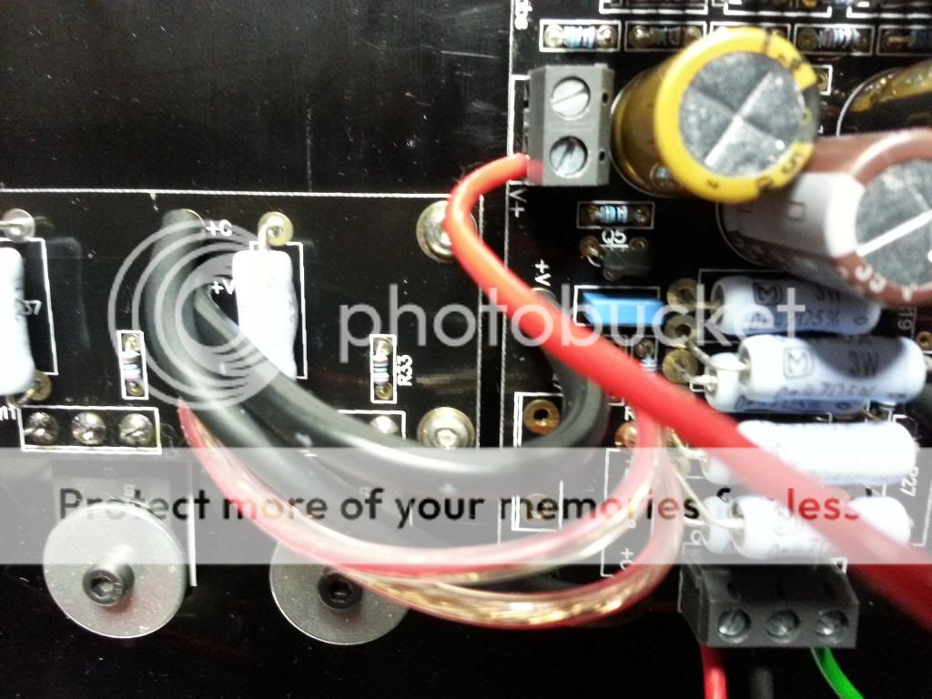
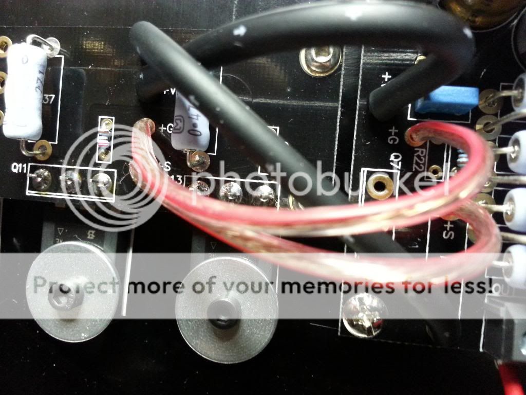
Please include close ups of the main board to output section connections.
Please include close ups of the main board to output section connections.
Please include close ups of the main board to output section connections.
Look at my last post, I've included the full res image as attachement
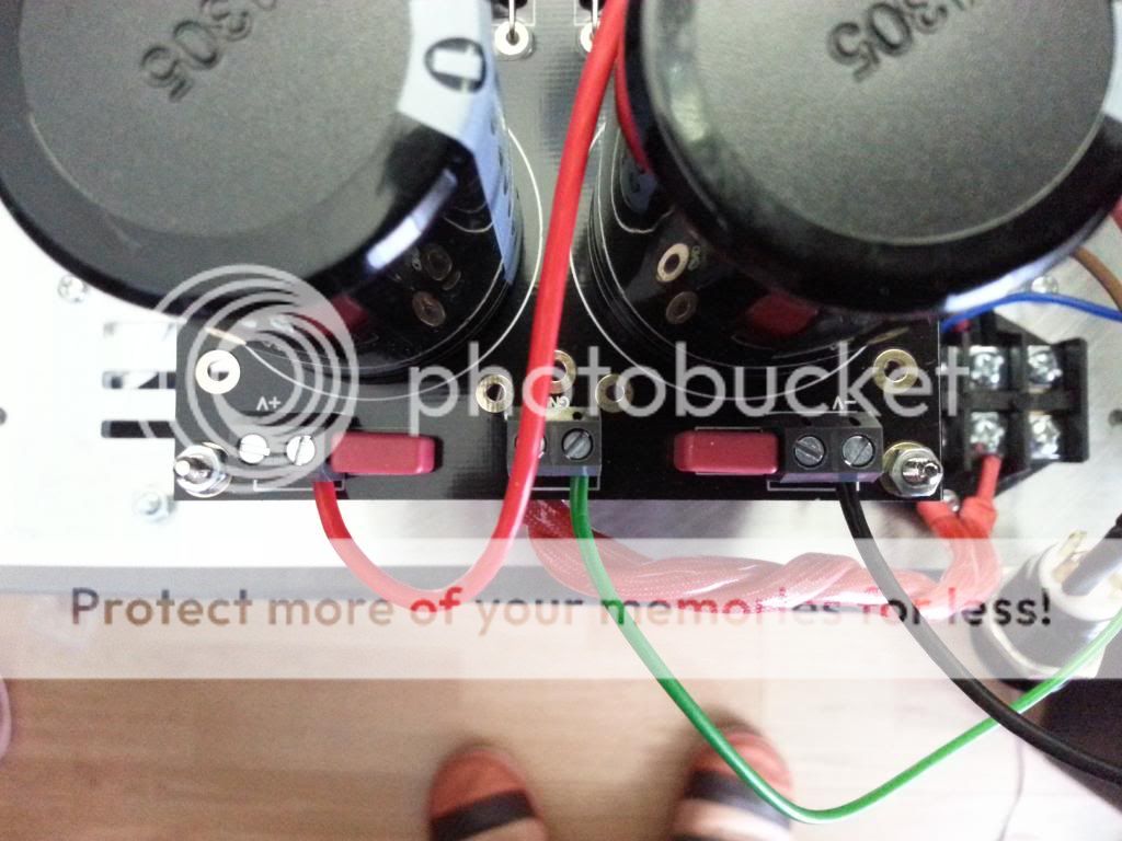
output connections on psu
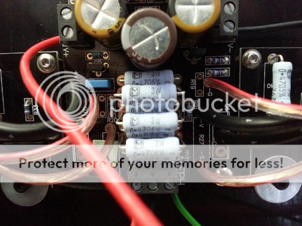
input connection on amp board (notice gnd green wire connected to Cgnd)
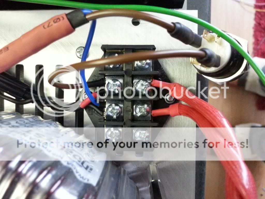
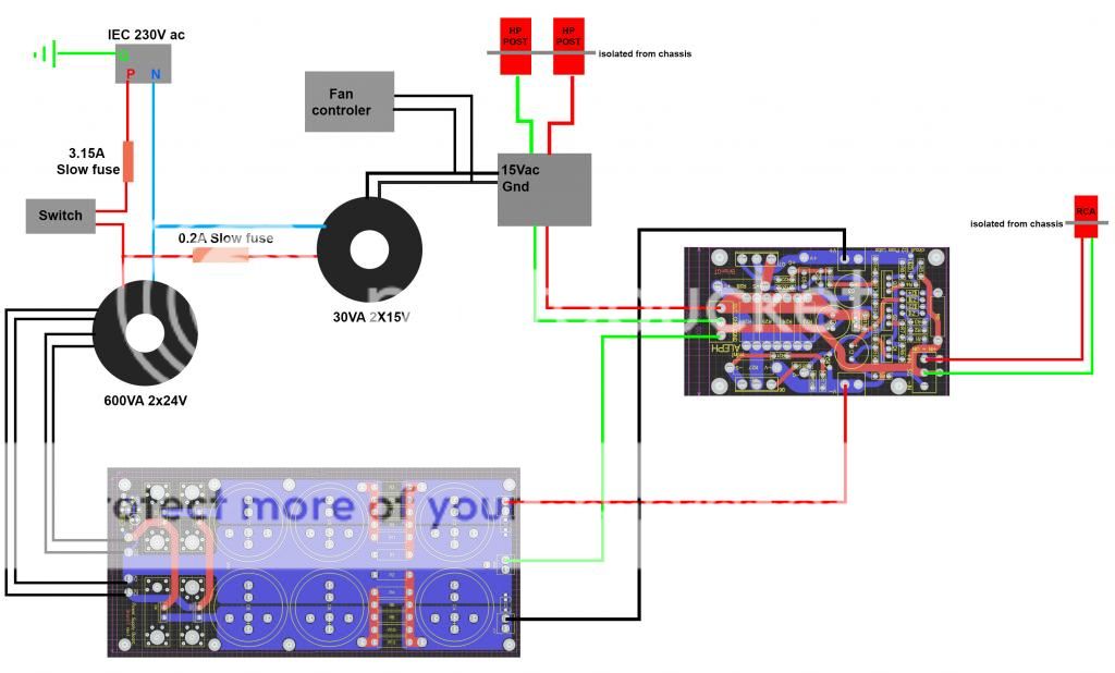
Main/power switch/trafos connections (blue is Neutral, brown Phase)
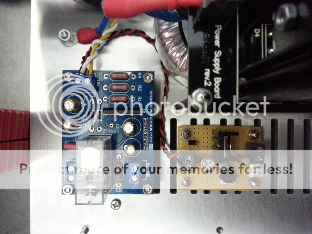
Speaker protection board and fan controller wiring (from 30VA trafo)
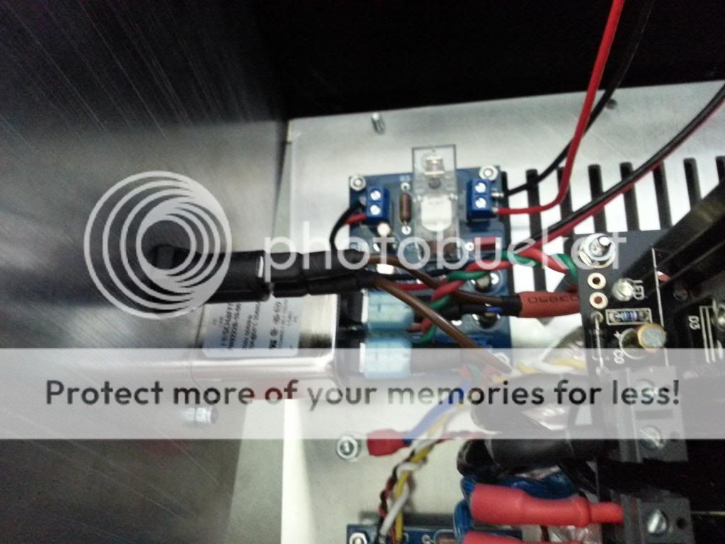
Main wiring (fuse linked to "P" of the iec inlet), notice the blue wire witch links IEC gnd to chassis
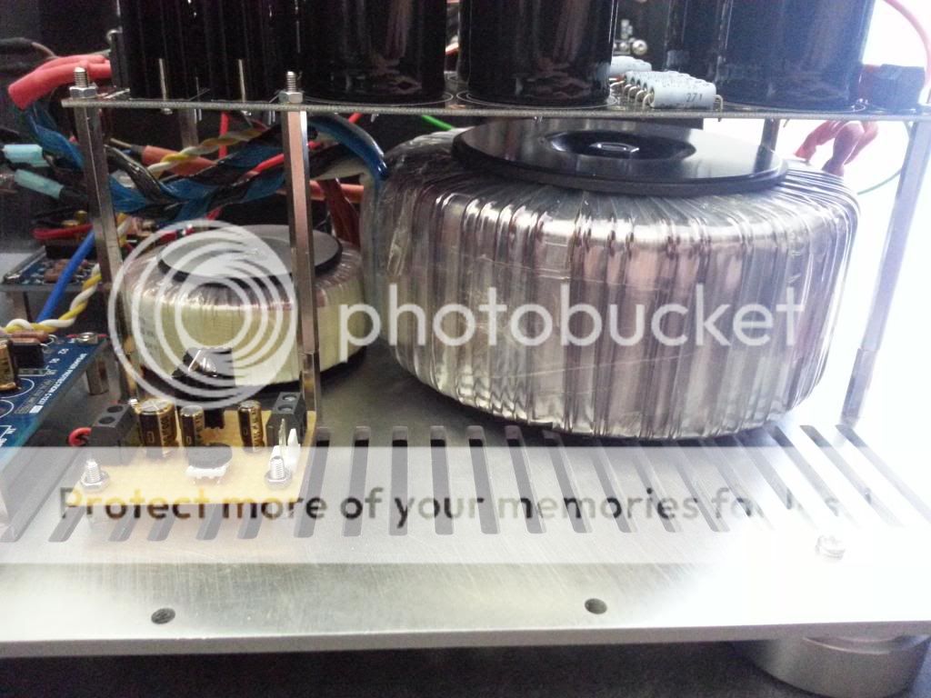
Overall pictures of the transformers
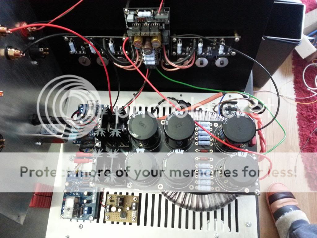
Overall picture of the amp in it's current state.
I know that wire are a little messy, but it's only a test rig, I'll attached and organize wires when all works
When I get some time later today I will pull out my boards and verify.
At this point though, I'd look hard for a short to ground.
Thanks for taking a bit of your time
How can I check for shorts? I used to check continuity between fets legs and exposed aluminum on the sink (or screws) and It never beeped
Ok, I've made new testings, and I discovered that the green wire witch goes from psu gnd to main amp board Cgnd was shorting the fets to ground, If i remove the green wire from the psu, the amp powers up, fan rotating and relays clicking, the psu outputs 32V dc;
however, I let it burn for say 4min, and the fets doesn't seems to warm at all.
however, I let it burn for say 4min, and the fets doesn't seems to warm at all.
same problem for both channels ?
anyway , few thoughts :
- you can't use bulb tester here in same way as for , say , F5 ; difference is that in most cases we are going with F5 unbiased at all , but that's not the case with Alephs ; so - you can use bulb tester there only for testing unloaded PSU
- amp pcbs : check with ohmmeter what's happening - resistance between rails and both gnd and output
- be precise when writing any value ; "the psu outputs 32V" is not precise , if you didn't wrote "per rail" etc. ; same for "shorting fets to gnd" ; fets are having 3 legs , and I can't be sure what you are thinking with that sentence
TEST2: Continuity
On unloaded psu:
Probes on V+ and Gnd = continuity (beep) resistance begins at -150R then goes up, the beep stops at nearly 50R and multimeter stops displaying resistance when it reaches 200R (I think it's due to the capacitors)
Same thing on V- and Gnd
TEST3: Continuity
On Amp board V+ and V- inputs (not connected to psu)
V+ to +V (on header board) = continuity
V+ to Fets (irfp240) "D" = continuity
V+ to OUT = no continuity
V+ to Gnd = no continuity
V+ to Cgnd = no continuity
V- to -V (on header board) = continuity
V- to -S (on header board) = continuity
V- to Header board res = continuity
V- to Fet (irfp240) "S" = continuity
V- to Q1 (irf9610) "D" = continuity
V- to OUT = no continuity
V- to Gnd = no continuity
V- to Cgnd = no continuity
Last edited:
TEST2 is redundant , considering results of TEST1
considering that I'm really not familiar with those pcbs and that BobEllis is having them , I hope his input will result in something
please - clarify "V- to Q1 (irf9610) "D" = continuity"
There's continuity between V- amp input and Q1 drain (Q1 is one of the three irf9610 fets on the board)
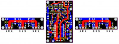
Here's a reference picture of the amp board, It will be easier to know what i'm testing.
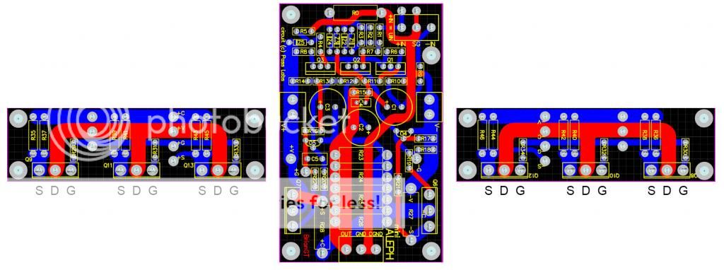
Attachments
Last edited:
aha
found schematic from start of the thread
D of Q1 is on neg rail
so , I'm not reading anything wrong in your measurements
so , waiting for Bob
found schematic from start of the thread
An externally hosted image should be here but it was not working when we last tested it.
D of Q1 is on neg rail
so , I'm not reading anything wrong in your measurements
so , waiting for Bob
- Status
- This old topic is closed. If you want to reopen this topic, contact a moderator using the "Report Post" button.
- Home
- Amplifiers
- Pass Labs
- Beginner to build an Aleph30 needs some help
