I've been lurking on this board for years and I finally thought I would dive in a give it shot at building my own amp. I'm the type of person who usually figures things out by taking things apart, I've got a pretty decent amount of experience with basic electrical and most of my electrical experience comes from HVAC and building automation and controls. I've a very rough idea of how this amp works and I am fairly confident I can put it together and have it work, but the main goal here for me is figuring out what the purpose of each componant in this amp is.
I only purchased the componant kit, not the enclosure or power supplies. I've been wanting to give building amp a shot for a while now, so I've been collecting parts and putting them aside just incase.
I only purchased the componant kit, not the enclosure or power supplies. I've been wanting to give building amp a shot for a while now, so I've been collecting parts and putting them aside just incase.
Attachments
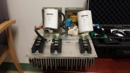
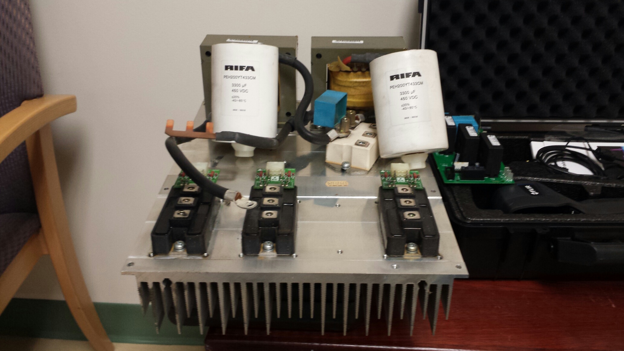
All kidding aside, I'll probably only being using the heatsink as a temporary test bed, possibly the recitifier as well, again just for testing. The two chokes and the capacitors, if they ever get used will be for novelty use only. ")
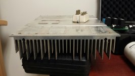
The heatsink (16"x12"x3"), I'm only going to use to test out the amp(s) until i can build a proper enclosure. Though I am tossing around the idea of cutting it down and using it as a base with the fins as legs. Given the size and mass of this thing, I'm guessing heat disappation won't be an issue even with the fins down.

The heatsink (16"x12"x3"), I'm only going to use to test out the amp(s) until i can build a proper enclosure. Though I am tossing around the idea of cutting it down and using it as a base with the fins as legs. Given the size and mass of this thing, I'm guessing heat disappation won't be an issue even with the fins down.
Attachments
Last edited:
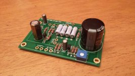
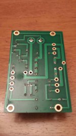
Here is what I actually have completed so far, this is the first time I've done more than basic repairs on a circuit board, and I think it came out pretty good. I know some people soldered the 2.2k resistor to the back side of the board but when I was laying it out that way it made me twitch. To get both componants in the same hole I ended up using a oxy/acetylene tip cleaner/reamer to open up the holes a hair. Since I did remove a bit of copper in the hole that connects the trace from the back to the front of the board, I made sure I soldered them on the front and back. And since having just a couple componants soldered on both side also made me twitch, I went ahead and soldered everything I could from both sides. Whether or not that decision comes back to bite me in the rear has yet to be determined.
Attachments
Oh and incase anyone is wondering, all of the "collected parts", came from a variable frequency drive for a 460v 3phase 50hp supply fan motor, that bit the dust during a thunderstorm several years back.
For the first of what will probably seem like stupid questions to me looking back... I know the kit specs a 19v power supply, but how flexible +/- is that voltage range?
For the first of what will probably seem like stupid questions to me looking back... I know the kit specs a 19v power supply, but how flexible +/- is that voltage range?
Last edited:

go back - you can find all sorts of , even extreeeeemely dumb , questions - written by Mighty ZM
No dumb answers, as I recall.
Hopefully, I'll be able to finish soldering the other board this weekend. I was hoping to be able to find a psu at work this week but things were just to crazy. The IT dept is changing out a bunch of equipment, and there are several different types of power supplies for me to go through.
I'd still like to build own power supply, I'm mainly looking for something to test with.
I'd still like to build own power supply, I'm mainly looking for something to test with.
I finished soldering, the second board to the same state as the first. I don't really want to go any further until I figure out what I am going to do for an enclosure.
I'm thinking about doing a single enclosure and power supply. Rather than a full sheet metal enclosure, I'll probably go with wood on the top and sides. What things should I take into consideration when putting both boards and power suppply in a single housing?
Do I need to think about only separation distance, or should I consider using a sheet metal divider between componants such as the power supply and the amplifiers.
And as far as using wood is concerned, would it be a bad idea to line the interior with a metal foil for shielding?
I've made a little more progress yesterday, I mostly finished soldering the boards, and the only thing left is for me to add leads for the output. I found at work a 120v primary 17v 5a / 5v 1a secondary transformer that I think I can use for a power supply.
I know it wouldn't be the cleanest power source, but could I hurt anything by running it through just a rectifier? At least for testing purposes though. I plan on cleaning it up a little though once I start fitting everything to an enclosure.
I know it wouldn't be the cleanest power source, but could I hurt anything by running it through just a rectifier? At least for testing purposes though. I plan on cleaning it up a little though once I start fitting everything to an enclosure.
I also took a trip up to an electronic surplus store that I've been wanting to find any excuse to go back to. I picked up a couple 25a rectifiers, and found a new toroid transformer that I'll probably plan my next project around. It seemed like a deal for $25. The specs on it are 120v pri/ 20.5v dual sec rated at 5a each leg. There is no markings on it only a hand written tag with a wiring diagram, and a model number that I need to try and look up.
just a rectifier .........
yes , as long you have C bank after it

Well, power supplies are an area that I know only the basics about. But I have been reading some of the stickies in the power supply section.
I can get something appropriate if need be, but if can use them for now, I have a handful of 250v caps (470uf, 220uf, and 100uf), and I also have an assortment of 1/4w resistors. From what I am reading, a snubber is tuned to a transformer, but can I make anything "useable" with what I have?
Oh and the toroid I picked up looks to be made by a company called Talema. 008-0050171
Last edited:
- Status
- This old topic is closed. If you want to reopen this topic, contact a moderator using the "Report Post" button.
- Home
- Amplifiers
- Pass Labs
- Newbie ACA build!