that autoformer volume is one of the best sounding around....
I prefer cheaper ones ,intended for 16 pos. switch
I prefer cheaper ones ,intended for 16 pos. switch
Balanced autoformer volume control are interesting option as well.
Autoformers can deliver additional gain too if necesairy.
After my Aleph J first fire on i just connected iPad without preamplifier.
They have gain in and digital volume control so it's work puzzle.
Ok this is not professional audio card or dac but quality is ok for experiment.
After that i connected tube preamplifier who have switches for impedance choices and bias but surprise i discover that additional pre box with his cables
just missing sound transparence clarity i find with simplified audio signal chain
iPad + amplifier + full range.
Maybe autoformer mixture with Luminaria or with 2SK79 can do the job ?
Greetings
")
Adding some warm sound....
Hi Soundhappy and everyone.
I have been living happily with my Luminaria without Buffer(only last stage) through my mono LÀmp. It is way more gain than needed (only 11 O`clock volum to high SPL). To my Alpair 12P . But I sometime miss some warmer sound - and now is searching for maybe a tubebuffer since some think a tube gives a fuller, warmer sound.
But you said:
"After that i connected tube preamplifier who have switches for impedance choices and bias but surprise i discover that additional pre box with his cables
just missing sound transparence clarity i find with simplified audio signal chain"
And taht made me thinking - did you buffer a Luminaria or what?
I have found a really inexpensive buffer that could make some improvement that I will try:
Best to all!!
Olav
Hi Soundhappy and everyone.
....And that made me thinking - did you buffer a Luminaria or what?
I have found a really inexpensive buffer that could make some improvement that I will try:
Best to all!!
Olav
Hi Olav
It was experiment without any preamp or buffer connected just digital audio source iPad connected directly to amplifier with full ranges speakers
I was thinking about mix of autoformer ,Luminaria and L'Amp together
to build " ultimate one box integrated single-ended SIT amplifier " for reduce numbers of components, chassis , wires, connections cables & etc.
Plug and play integrated version : autoformer volume control , sit preamplifier
if need ( switch on / off) and finaly sit 2SK82 power stage.
2SK79 gyrator loaded preamp
Not yet built, but I think simulation result is promising enough for a build.
Since now member liubincalvin (supposedly selling remaining zhoufang stock) offers the 2SK79 in matched pair here, I went on trips to Simuland a few days ago and got interesting result.
Design is a variant of ZV2, using a simpler gyrator instead of aleph current source.
0.003439% THD at 1Vrms
0.032589% THD at 10Vrms
I'm in the process of acquiring parts. Please comment if you see any mistake, error and opportunity for improvement.
Will share simulation files if anybody is interested.
... Come on, show us what is possible with the 79s...
Not yet built, but I think simulation result is promising enough for a build.
Since now member liubincalvin (supposedly selling remaining zhoufang stock) offers the 2SK79 in matched pair here, I went on trips to Simuland a few days ago and got interesting result.
Design is a variant of ZV2, using a simpler gyrator instead of aleph current source.
0.003439% THD at 1Vrms
0.032589% THD at 10Vrms
I'm in the process of acquiring parts. Please comment if you see any mistake, error and opportunity for improvement.
Will share simulation files if anybody is interested.
Attachments
I remember Mr Rothacher modify Luminaria with 2SK79 small signal vfet´s.
Matched pair that nice . Do is worst to try ?
http://www.diyaudio.com/forums/vend...uding-some-very-rare-toshiba-transistors.html
Thanks for the link
Matched pair that nice . Do is worst to try ?
http://www.diyaudio.com/forums/vend...uding-some-very-rare-toshiba-transistors.html
Thanks for the link
that autoformer volume is one of the best sounding around....
After all time i spend experimenting with autoformer volume control my compare test's conculsion is :
i need buffer for impedance adjustement
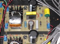
My Build
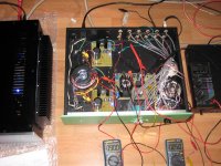
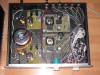
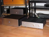
Until about a year ago I was all tubes. Then I heard about Sony VFETs and the DIYAudio/Pass Sony VFET amp, so I got in line and managed to get one. Now, my diy 45 mono amps and 26 preamp have been replaced by VFETs: a DIYAudio/Pass Sony VFET amp, a 193V 2SJ28 L'Amp, and a Luminaria preamp.
I managed to obtain the 2SK82s while I was browsing ebay late last year when fortuitously, Acronman had just put up eight for sale. I bought two and that enabled me to construct the Luminaria.
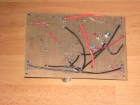
I wired it all up point to point on VeroBoard. The input volume control is a pair of S & B TVCs that had been in my system for years. I omitted the option of separate buffer and gain stage, and connected the buffer directly to the gain stage, thereby eliminating one coupling cap per channel. In place of the output volume control I have a 5K resistor. I may replace that with a coarse diy three position resistor ladder pot to experiment with later on.
Since I only had two unmatched VFETs, I added an 100 ohm trimmer pot in series with a 560 ohm resistor to provide the drain resistance. Because I do not have any equipment for distortion analysis, I set Vds at 90 volts and I at 50mA and figured that should put me in the ball park. Initially one channel had the drain resistance at about 635 ohms and the other channel at 655 ohms. After several days both channels ended up at about 660 ohms. The buffer MOSFET source resistor was also tweaked to get 7mA through it.
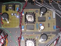
The coupling caps are Vishay polyethylene MKP1848 DC Link. I chose them based on price and availability since I wanted to purchase all the parts from only one supplier (Mouser). I know that they are power supply caps but hey, motor run caps are power supply caps and I use them for signal too. I started out listening with only the Vishays in place and I liked the sound. I have since added various bypass caps that I had on hand and I think there has been some improvement. The input capacitor has been replaced with an Auricap and the input Vishay has been used to bypass the Silmic electrolytic at the 2SK82 source resistor location. However, I think the good sound is due to the VFETs and Michael's design more than anything else.
In my system the Luminaria adds another level of realism to music. Thank you, Michael for giving us this design. Also thanks to those whose contributions to this thread have provided me with ideas on building this preamp.
Until about a year ago I was all tubes. Then I heard about Sony VFETs and the DIYAudio/Pass Sony VFET amp, so I got in line and managed to get one. Now, my diy 45 mono amps and 26 preamp have been replaced by VFETs: a DIYAudio/Pass Sony VFET amp, a 193V 2SJ28 L'Amp, and a Luminaria preamp.
I managed to obtain the 2SK82s while I was browsing ebay late last year when fortuitously, Acronman had just put up eight for sale. I bought two and that enabled me to construct the Luminaria.
I wired it all up point to point on VeroBoard. The input volume control is a pair of S & B TVCs that had been in my system for years. I omitted the option of separate buffer and gain stage, and connected the buffer directly to the gain stage, thereby eliminating one coupling cap per channel. In place of the output volume control I have a 5K resistor. I may replace that with a coarse diy three position resistor ladder pot to experiment with later on.
Since I only had two unmatched VFETs, I added an 100 ohm trimmer pot in series with a 560 ohm resistor to provide the drain resistance. Because I do not have any equipment for distortion analysis, I set Vds at 90 volts and I at 50mA and figured that should put me in the ball park. Initially one channel had the drain resistance at about 635 ohms and the other channel at 655 ohms. After several days both channels ended up at about 660 ohms. The buffer MOSFET source resistor was also tweaked to get 7mA through it.
The coupling caps are Vishay polyethylene MKP1848 DC Link. I chose them based on price and availability since I wanted to purchase all the parts from only one supplier (Mouser). I know that they are power supply caps but hey, motor run caps are power supply caps and I use them for signal too. I started out listening with only the Vishays in place and I liked the sound. I have since added various bypass caps that I had on hand and I think there has been some improvement. The input capacitor has been replaced with an Auricap and the input Vishay has been used to bypass the Silmic electrolytic at the 2SK82 source resistor location. However, I think the good sound is due to the VFETs and Michael's design more than anything else.
In my system the Luminaria adds another level of realism to music. Thank you, Michael for giving us this design. Also thanks to those whose contributions to this thread have provided me with ideas on building this preamp.
Attachments
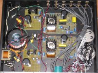
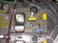
Fixed Bias Luminaria
Michael had written that although fixed bias is not necessary to enjoy the sound, it is worth the effort. I have been enjoying my Luminaria with a source resistor but hey, this is diy so effort is no charge. I decided to redo my Luminaria with fixed bias.
For the bias supply I used one transformer and rectifier bridge to supply both channels, and provided each channel with a LM337 regulated supply.
I removed the source resistor and capacitor and re-positioned the resistor to the drain side in front of the load resistor, with a decoupling capacitor added. I decided to try a slightly higher Id at 55mA this time, with Vds at 83volts. The Vbias ended up at -16.1v and -17.9v for right and left channels respectively.
It was worth the effort. At this level the gains are sometimes small yet large. To me, fixed bias added that extra little bit of clarity that made the music seem that much closer to reality. I noticed the effect especially on recorded live performances in that applause and audience sounds seemed more realistic and alive.
So far I have just been ball-parking the operating points based on Michael's general recommended operating range. I have a Focusrite Scarlett 2i2 coming to me in the mail so soon I will be able to try to see if I can select some operating points quantitatively. So maybe more performance gains to come.
Attachments
Hello Mike,
Do you think I can use this 1pc THF-51S TOKIN V-FET(SIT) (similar 2SK77,2SK180) NOS Original, Japan Made | eBay for the luminaria?
Bao
Do you think I can use this 1pc THF-51S TOKIN V-FET(SIT) (similar 2SK77,2SK180) NOS Original, Japan Made | eBay for the luminaria?
Bao
Nice work!
Thanks, Michael.
It was a fun build and the point-to-point wiring made changes easy to do.
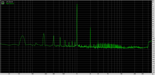
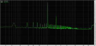
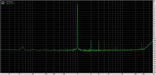
I received my Focusrite Scarlett 2i2 the other day so I did some spectrum analysis today. I used the Focusrite and Right Mark Audio Analysis software to produce the 1kHz input signal for the analysis. The signal was sent through the whole preamp, from TVC to buffer stage to VFET output.
Initially I found a huge 60Hz bump and harmonics. It was due to my diy unshielded cable that was going from the Focusrite output to the preamp input. I moved the cable as far away from the preamp AC line as feasible and that dropped the 60Hz and harmonics considerably.
I found that the right channel was noisier and had higher distortion than the left. I played with the drain load resistance and the bias but that only made a small change in the second harmonic.
I will also make a shielded cable and try again to see if that will lower the noise some more.
Hopefully the results are somewhat meaningful. This is my first attempt at spectrum analysis and my test rig is hobbyist grade, plus there could also be user error. But I think the results do give a ballpark look at the preamp's performance.
Left and right channel spectra and Focusrite loopback spectrum below:
Attachments
Last edited:
- Home
- Amplifiers
- Pass Labs
- Luminaria?