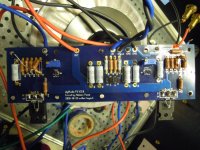
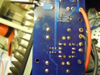
Hi to all. I've built my new F5 power amp but I can't measure voltage through R11 and R12. I've found few errors Q5 and Q6 were placed in ebc cbe wrong position and my soldering iron had 30-40v on the tip. The rail voltage is ok 23.5v. Is the ground wiring important in this step. Can an error in grounding affect the voltage? Following a guide I've added 2.2k resistor to R3 and R4 but...
Attachments

post exact schematic you're reffering to
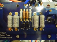
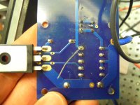
your soldering is somewhat messy - wires needs more solder , additional resistors aren't looking as soldered at all
besides that - with repeated color of wires , one need to have extensive experience , to not mix things
confirm both PSU polarities present on pcb , same as proper gnd from PSU
confirm that you mount functional Jfets on pcb ;
from where you purchase them ?
cviller 2.0 boards and JojoD818 build guide;
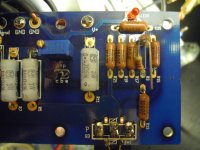
about the colors in this step I'm wiring only v+ v- gnd
Are you coming out from my usb port? Now I do have voltage and mosfet are warming!!!
Perhaps I really needed more ohms and at first the resistors were badly soldered. Now when I put full voltage to the board the voltage through r11 starts from 0.3v and rapidly goes up to 0.5. Then I disconnected the voltage cause the trans are not heatsinked. I have to solder the resistors to mount the board. Can I keep these resistors values?
keep new resistor values - trimpots are dominative
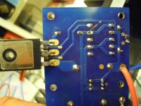
check all solder points , check isolation of mosfets from heatsink , when you finish mounting
be sure that they're screwed firmly
find any of F5 biasing procedure tutorials , and read it several times - please
ground inputs during entire setting procedure
check all solder points , check isolation of mosfets from heatsink , when you finish mounting
be sure that they're screwed firmly
find any of F5 biasing procedure tutorials , and read it several times - please
ground inputs during entire setting procedure

- Status
- This old topic is closed. If you want to reopen this topic, contact a moderator using the "Report Post" button.