") as far as i remember, 8mA is about minimum for 4 output pairs.
as far as i remember, 8mA is about minimum for 4 output pairs.Well, I have one yes and one no. Anybody else have an opinion?
Since you're adding capacity by paralleling more output devices, the output slew rate will suffer unless more drive is available. Not a show stopper, but undesirable for best fidelity.
The following is the brief discussion about adding parallel output stages by NP from the F5Turbo paper:
“That said, the capacitance of the output stage devices starts to pile up and the bandwidth starts to go down. If I can get 800 Khz bandwidth from this amplifier with 2 pair of devices, then I might expect something on the order of only 80 Khz from 20 pair.”
I assume that this is the slew rate issue that fpitas talked about. It seems that with 6 sets of output devices I could expect a bandwidth of 800 Khz/3 = 266Khz. That seems to me to be more than adequate for my use.
“Even this is not much of a barrier – we simply parallel input Jfets to raise the current available for driving these devices and decrease the impedance of the feedback loops. After about 4 sets in parallel you need to give them Gate resistors to avoid parasitic oscillation and you are good to go - probably to 500 watts or so into 8 ohms and more into lower impedances.”
Is the “4 sets in parallel” NP is talking about four sets of input JFETs in parallel or four sets of output FETs in parallel? I’m guessing he means input JFETs so this wouldn’t apply to me if I used 2 sets of parallel input JFETs.
Is the “decrease the impedance of the feedback loops” NP talks about mean changes that I need to make to feedback resistors? Which resistors and how would I go about calculating new values?
So back to my original questions;
1. If I can live with the ~266Khz bandwidth (I can), can a single pair of input JFETs drive sufficient current for six pairs of parallel output devices?
2. If a single pair of input JFETs can’t handle six output pairs, how do I go about modifying the schematic to add parallel input JFETs? Do I literally just put the additional JFETs in parallel with the current devices or are there additional components I need to add or change value?
If you match the input JFETs reasonably closely, you can probably get away with just paralleling them; but it probably wouldn't hurt to add individual source resistors of a few ohms (say, 3.3 ohms).
fpitas - Thanks for the response. Can I infer from your post that you don't think a single JFET pair could drive 6 output pairs?
fpitas - Thanks for the response. Can I infer from your post that you don't think a single JFET pair could drive 6 output pairs?
Not exactly. It's a matter of viewpoint, and what's "good enough", which is why you got yes and no answers. If I was building my own amp, I'd be very concerned about fidelity; but that's because I wouldn't bother building my own unless I thought it would turn out exceptional.
NP was referring to gate resistors on the jfets. The output devices already have them. You could probably get away without individual gate resistors with two pairs.
I'd go for 2 pairs of input devices, to get as close to the design sound, keeping the bandwidth as wide as possible. Even though 250 KHz seems reasonably high, rolloff and phase changes start well below that. But fpitas is correct, it is a matter of personal taste and what is "good enough."
I'd go for 2 pairs of input devices, to get as close to the design sound, keeping the bandwidth as wide as possible. Even though 250 KHz seems reasonably high, rolloff and phase changes start well below that. But fpitas is correct, it is a matter of personal taste and what is "good enough."
parallel input Jfets to raise the current available for driving these devices and decrease the impedance of the feedback loops.
Zen Mod - are you saying that I would also have to change feedback resistor values?
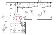
I took a peek at the F5T schematic; the feedback is returned to the input JFET sources. To keep the same voltage gain with two pairs of JFETs there, you'll need about half the value of feedback resistor. Is that right, ZM?
seems that's what Papa meant (disregarding the fact that I'm having same idea )
to keep same source degeneration (in fact ratio of Rd/Rs) of two pairs vs. one pair , one need to put halved (common) Rs for Jfets , considering that you'll have also halved Rd ( to open output mosfets )
that means feedback resistors ( going from output node to sources of upper/lower Jfets) must be halved too
so - staying in so-so same ratio of OLG vs. CLG
take care of feedback resistors wattage ...... or just double (parallel ) same ones as prescribed in common schematic
in short - parallel input Jfets , along with their Rs ; parallel Rf
Last edited:
- Status
- This old topic is closed. If you want to reopen this topic, contact a moderator using the "Report Post" button.
- Home
- Amplifiers
- Pass Labs
- Six output pairs with standard F5T front end?