I decided to implement the version 1.0 circuit in my amplifier for the following reasons:
- I do not have +/-15vdc rails available elsewhere.
- I do not need high input impedance.
- I do not need high input voltage capability.
- It avoids surface mount components.
- The parts count is lower.
I modeled the version 1.0 circuit using ngspice first to refine component values. The only changes I made were:
- Q4 was changed to a MJE3439G, which is rated for the rail voltages that could be present in my amplifier. The BD139 would have been slightly under-rated.
- R3/R4 were changed from 2.5k to 3.0k.
- C1/C2 were changed from 22uF to 10uF.
I built the circuit on a breadboard, and the performance essentially matched the ngspice simulations. The DC offset trigger voltage is approximately 2.3v. The relay coil releases in about 60ms in response to a large step increase in DC offset.
SpeakerProtection Photos by turbotoy24 | Photobucket
Next is to design a PCB for the circuit (for my use only). I have never done PCB design work before, and thought that this would be a good project to start with. One board will contain a single detector pair and driver and two relays, one for each phase. Two boards will then be used for a stereo amplifier.
A significant thank you to Patrick for publishing this circuit!
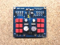
Prototype board tested today. Works first time.
Even with a 100Hz 20V p-p sine wave (as music signal) superimposed on top, the trigger works as planned.
With +/-3.3V DC, protection trigger takes place in about 4s.
With +/-4V DC, protection triggers in 1s, as designed.
One can easily change the sensitivity to e.g. +/-2V by changing the source resistors of the diff pair.
Patrick
Attachments
The Omron G2R series has a maximum DC contact rating of 10A@30VDC. Seems that under severe output failure this relay is totally inadequate. I am interested in protection circuits that will not weld the contacts ? Seems the core device, the relay, is most often of secondary consideration ?
purpose of circuit is exactly that in serious output failure current isn't going through relay contacts
you can call it relay protection module

Maybe I am looking at the wrong schematic. AMP OUT+ and SPEAKER+ are switched by the relay contacts. Output DC failure clearly goes through the contacts to the Speaker( Load) and this is what is being interrupted resulting in a DC arc.
The G2R relay mentioned in the first article is only an example to illustrate the circuit.
You can choose any relay you wish and adjust the current of the relay driver to suit the coil.
The G2R single pole high current version can switch 16A resistive.
Under normal operation, I tend to think it is more than sufficient.
In the F5X project, we do use automotive relays.
You can get those up to 70A rating.
The purpose of the circuit is to disconnect the loudspeaker in case of a faulty DC voltage at the output of the amplifier.
At 4V DC (as it stands), the maximum current for a 4 ohm speaker is 1A.
I cannot see how that can be an issue for the relay.
And I would also think that most speakers can also live with 4W dissipation even if DC.
If you want over current protection (e.g. against output short circuit), then you need to use something else.
Patrick
Last edited:
Yes, you are right 16A@30VDC.
Before the circuit reacts at 4VDC, the output has climbed to the rail voltage, the high current is flowing.
Automotive relay contact ratings are a lot less then 50VDC. I am talking about operating the relay within specification.
DC is notoriously difficult to interrupt and once the arc strikes, it is fatal to the contacts. Interrupting a reactive load (speaker) at DC can create a very large potential across the contacts (greater then the rail voltage) to get things going.
Maybe I am looking at the wrong schematic. AMP OUT+ and SPEAKER+ are switched by the relay contacts. Output DC failure clearly goes through the contacts to the Speaker( Load) and this is what is being interrupted resulting in a DC arc.
You are absolutely right.Yes, you are right 16A@30VDC.
Before the circuit reacts at 4VDC, the output has climbed to the rail voltage, the high current is flowing.
Automotive relay contact ratings are a lot less then 50VDC. I am talking about operating the relay within specification.
DC is notoriously difficult to interrupt and once the arc strikes, it is fatal to the contacts. Interrupting a reactive load (speaker) at DC can create a very large potential across the contacts (greater then the rail voltage) to get things going.
In the time from detecting that output is becoming offset to the time that the relay contacts actually try to open, the current will already be flowing and the PSU will be discharging rapidly through the speakers (or to a short).
The isolation medium has to break the DC fault current, assuming the PSU is doing it's best to recharge itself while the Mains fuse has still not ruptured.
This is where a close rated Mains fuse will rupture much more quickly than the BIG fuses many of us Builders habitually use.
You can always shunt the amp output with an Omron G8P or 70A automotive relay and replace it afterwards (contacts will be welded).
The speaker will be saved, at the expense of your output stage.
But if that gives out a 4V DC something needs replacing anyhow.
The trigger time will shorten drastically when the DC is higher than the design value.
See post #22 for real-life data rather than theoretical discussions.
Alternatively you can also use the relay to switch off the supply to the amp after the regulator caps.
On top of that you can also put a current limit on the regulator.
(This will be the case for the F5XP regulator.)
If you want comprehensive protection then you should use the F5X protection architecture.
The protection board for the F5X switches off a multiple of things to save the speaker and minimise damage to the amplifier.
But it is no long a simple thing like the circuit posted here.
So you can pick your poison.
For me personally, to have no protection at all is no option.
Or you have a much more clever solution to share with us ?
Patrick
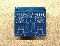
A short note for those using the V2 PCBs :
For power supply you require min. +/-18V 50mA.
There are 7815/7915 regulators on board, with capacitors before and after.
So a rectifier after the transformer is sufficient.
The Gnd of your amplifier should be connected to the mid-point of the protection circuit power supply via a 1k resistor.
There are two relay connections and two detection circuits.
Unused relay connections can be left unconnected (isolated to prevent accidental short circuit).
Unused detection inputs should be tied together to prevent unwanted trigger.
Patrick

Someone asked by PM about the V2 proto test.
I cannot quite understand :
1) why you wish to ask by PM and not post here ?
2) what additional information I can provide other than those from post #27 onwards ?
The fully functioning proto has been bought by one of the members here.
Another member is waiting for 2 boards, but shame on us, that my guys in HK is too busy to find time to ship for him.
So my apologies to him for the long, long wait.
Worst, worst case I shall ship it myself when I am there next, unfortunately probably December 2015.
Thank you for your interest nevertheless,
Patrick
- Status
- This old topic is closed. If you want to reopen this topic, contact a moderator using the "Report Post" button.
- Home
- Amplifiers
- Pass Labs
- Simple Speaker Protection for Power Amplifier with Balanced Outputs