I have done some simulations and it looks like the circuit of post #66 can be scaled up to 40V P-P AC output. A CCS load using a DN2540 allows higher output swing without increasing the rail voltages and reduces H2 and H3 by about 3:2 at all frequencies and power levels. I have not built and measured this yet, but parts will be ordered. The zeners were added to reduce the max voltage and power dissipated in the JFETs, but might not be needed. Below is the circuit that I simulated:
Attachments
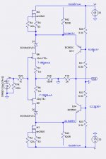
Zeners are not needed - without them the Vds is 23V and it doesn't vary a lot. Almost all of the voltage swing happens at R19. JFETs will dissipate about 170mW each and that's OK, but 300mW for each BC5x0c might be on the edge.
Check the Vbe of Q13 - it's almost 6.5V instead of 700mV.
Try to raise the value of R26 and listen the difference (and R19 proportionally, to preserve the gain ratio) - you have the buffer at F4's input anyway...
Check the Vbe of Q13 - it's almost 6.5V instead of 700mV.
Try to raise the value of R26 and listen the difference (and R19 proportionally, to preserve the gain ratio) - you have the buffer at F4's input anyway...
Oops, the voltage measurement for Q13's base was at the wrong node. LTSpice renumbers unnamed nodes whenever something is changed. I need to explicitly name all nodes with voltage measurements.Zeners are not needed - without them the Vds is 23V and it doesn't vary a lot. Almost all of the voltage swing happens at R19. JFETs will dissipate about 170mW each and that's OK, but 300mW for each BC5x0c might be on the edge.
Check the Vbe of Q13 - it's almost 6.5V instead of 700mV.
Try to raise the value of R26 and listen the difference (and R19 proportionally, to preserve the gain ratio) - you have the buffer at F4's input anyway...
I agree that the zeners are probably not needed. Without them I see a maximum voltage of 24.8V with 40V P-P output.
I also agree that I am pushing the limits on the power dissipation on the BC5x0C transistors. There are small heatsinks for TO-90 packages that might help. As you suggest, increasing R26 and R19 makes it possible to reduce the cascode current below 20ma, thus reducing the BC5x0C power dissipation.
The simulation distortion numbers look very good.
")
Most interesting. The LSK line stage amp and F4 add up to half the schematic of Fig 4 in US patent #5,376,899; which gave us Super Symmetry amplifiers.Zeners are not needed - without them the Vds is 23V and it doesn't vary a lot. Almost all of the voltage swing happens at R19. JFETs will dissipate about 170mW each and that's OK, but 300mW for each BC5x0c might be on the edge.
Check the Vbe of Q13 - it's almost 6.5V instead of 700mV.
Try to raise the value of R26 and listen the difference (and R19 proportionally, to preserve the gain ratio) - you have the buffer at F4's input anyway...
Not quite. Fig 4 in the Supersymmetry patent contains feedback. As presented, the LSK line stage does not use feedback.Most interesting. The LSK line stage amp and F4 add up to half the schematic of Fig 4 in US patent #5,376,899; which gave us Super Symmetry amplifiers.
You are right.Not quite. Fig 4 in the Supersymmetry patent contains feedback. As presented, the LSK line stage does not use feedback.
When I double the values of R26 and R19, to 4k and 360R, the distortion (from LTSpice) at high frequencies increases significantly. After further study, the 2sj74 in the F4 input buffer has fairly high Ciss and Crss capacitances of around 90pf and 30pf at Vds=-20V, and the 2sk170 has about 1/3 those capacitances. Looking at the JFET AC gate currents there is an obvious distortion component which is likely due to the bootstrapping of the JFET drains from the F4 output. Thus, it appears desirable that the folded cascode output impedance be as low as practical.Zeners are not needed ...
Try to raise the value of R26 and listen the difference (and R19 proportionally, to preserve the gain ratio) - you have the buffer at F4's input anyway...
lhquam,
of course, you got to find a sweet spot.
2sj103/2sk46 have much lower parasitic capacitance but a lower gm. BJTs have their charms too. The choice is wide, you got to find what you like - this weekend I tried j175/j301 as input pair at Id of about 20ma and Vds=10V and it's not bad at all...
of course, you got to find a sweet spot.
2sj103/2sk46 have much lower parasitic capacitance but a lower gm. BJTs have their charms too. The choice is wide, you got to find what you like - this weekend I tried j175/j301 as input pair at Id of about 20ma and Vds=10V and it's not bad at all...
... j175/j301 as input pair...
Typing error: the N-ch part is j310
I've been working in a slightly different universe with a similar circuit using J176 and PN4393 as gain elements at ~5ma current. I know you like the J310 (so do I, in some circumstances), but a better match might be between the J175 and high ranked PN4393 or lower ranked PN4392. These devices are short-channeled switching jfets that may be better complements than a device designed as a linear VHF amplifier. When I get a chance, I might try matching some, as I have hundreds floating around.
Of course, there are better matched parts and I didn't make an elaborate choice of these two JFETs - I just happen to have them in my parts bin.
So the scope of j175/j310 experiment was just the curiosity how will it sound (having in mind that due to cascoding only small part of transfer curve is exploited so the differences don't get the chance to become too big) and it's not bad at all...
So the scope of j175/j310 experiment was just the curiosity how will it sound (having in mind that due to cascoding only small part of transfer curve is exploited so the differences don't get the chance to become too big) and it's not bad at all...
Don't get me wrong, I simply think that it'll be easier to find matches with the J175/PN4393. Using what you have is not a bad way to go either if you can make it work. In my neck of the woods, I need 3 matched pairs per channel, as I'm going for a full 2-stage RIAA preamp and line amp. Those going for just a line amp don't need too much in the way of matching yield. I started out with J113 and J176, as these are also touted as "complements" (I also have a bunch), but the J176s I had on hand were too hot for decent matching with the J113s.
Setting the quiescent current to 10ma may allow more pairs from J175s and PN4393/J310, as well as reducing distortion/noise. I may back track and try this, even though I already have some J176s and PN4393s matched up.
Simulation sez that this gain stage should sound ok, as the harmonics are predominantly 2nd and 3rd, with the high orders down in the mud. It's nice to hear that your ears might be in agreement.
You are right, of course. It's just that I don't live in the USA and online shopping is a bit cumbersome for my patience/bureaucracy-tolerance level, so I tend to acquire what I can get without much hustle which is not always what I want/need.
I have a batch of j175 with Idss of about 45mA so using them at 10mA puts them in lower part of gm curve where they are even worse match for j310.
BJTs at input sound fine too and input caps don't scare me off. With some matching effort (bc560c/bc550c are 5 cents a piece here) and low input-to-ground resistor (10k) input caps can be avoided in the line stage but not so easily for phono-RIAA stage. Horses for courses...
- Home
- Amplifiers
- Pass Labs
- LSK pre - BAF 2013