What if the balanced source has already nasty output caps?
separate issue , isn't it ;
however , just to spoil part of Buzz's happiness :

Attachments
separate issue , isn't it ;
however , just to spoil part of Buzz's happiness :
As if 4 power supplies wasn't enough, you get closer and closer to the amp in the title

What is the output impedance of your buffer?He also used them coz he had them left from F6 amps ;-). What if you have an external buffer like B1, still need one in the front?
If it is less than 200 Ohms then should be no problem.
A bit random, but.. ZM, I was always wondering if there is a point of having this kind of symmetrical-balanced amp if all your sources are not balanced?
Definitely best to run a balanced source.
Main benefit I see of running balanced circuit with single ended source is power supply is not modulated with signal while in Class A, and you are able to create 4 x the power at the output working with low voltage parts eg sk70/sj74 ie no need for cascode
Last edited:
Concept bias PSUs
The schematic and pictures of the amp suggest the following for the biasing circuit:
A detailed schematic of this concept bias psu will follow.
As if 4 power supplies wasn't enough, you get closer and closer to the amp in the title
The schematic and pictures of the amp suggest the following for the biasing circuit:
- PSUs ride atop and are referenced to the power rails; but not to ground.
- May need to read and especially confirm the presence of the bias voltage on each SIT; which must be rock stable.
- Expect different bias voltages for the 4 SITs. This may require up to 4 PSUs [stereo] ; but one may get away with only two; one for each 23 V power rails.
A detailed schematic of this concept bias psu will follow.
Jensen transformer datasheet:
http://www.jensen-transformers.com/datashts/112lcf.pdf
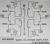
JT-112-L 2SJ28/2SK82=
 E=mc2
E=mc2
http://www.jensen-transformers.com/datashts/112lcf.pdf
JT-112-L
2SJ28/2SK82=E=mc2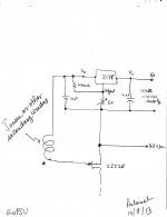
The approach which I posted is basically like the one you have already proposed in an earlier post and in the F6 thread; but simpler.it's best to situate each of these 4 wall mounted PSUs in different room ;
that way , sound will be more diffused and spatial
Last edited:

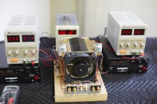
Mr Nelson Pass on this photo explain signal path of this amplifier maybe?
Like fingers up together is two sit's
and thumb is transformer
it is Pa one hand schematic clap?
photos courtesy AR2
Have nice day
Like fingers up together is two sit's
and thumb is transformer
it is Pa one hand schematic clap?
photos courtesy AR2
Have nice day
Attachments

Well, the sleazy fake version of this amp will be not be anywhere near so simple (most certainly not 3 parts - not anything near that), but I'm going to try and limit the pot-tweaking for the power supply to one pot, and limit the supply to one decent center-tapped transformer. At present, I've gotten a simulation to DC balance. I'll look at distortion and actual implementation later, as I have other audio fish to fry (record reviews). Oh yes, and the real details will be in another thread entirely, so as not to dilute this one.
Mr Nelson Pass on this photo explain signal path of this amplifier maybe?
....
nope , he's saying : "ZM's coffee mug is this big , 3 times a day ..... so that's why there is no night ! "
btw. Pa is cheating - he's using just half of heatsink , for stereo

Nelson's done a fine job showing just how linear these babies can be even in a 'native' state.
That said, this looks Ike a placeholder of sorts like we get in many of his articles.
The output impedance in particular would be happy to get some attention - at 4 ohms (based on the talk), it seems to fall into a strange twilight zone between a voltage source amp and a current source amp. I'm staying tuned for the next episode of .....
- Status
- This old topic is closed. If you want to reopen this topic, contact a moderator using the "Report Post" button.
- Home
- Amplifiers
- Pass Labs
- Ultrasimple SIT PP amp from BAF , or SIT Beast with a Thousand PSUs