There's been some time since I've got 2 pairs of k60/j18 VFETs (thanks to sstrsat and bata bane) so I had no choice - bulding a VFET amp became unavoidable for me  . First i did a nice little SE 5-Watter to get the hang of VFETs and the result was sonically very encouraging but I wanted something more powerfull.
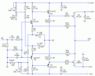
Here is what I came at: complementary BJT input (Q1,Q2) stage with adjustable Ic (to adjust VFETs' Vgs, Id and DC offset at the output) followed by EF stage (Q3, Q4) that provides a low impedance drive for VFETs which are used in common source connection (drain follower, i.e. voltage and current gain). Feedback is done F5-style (so called "CF") for the CLG of about 20dB.
Before you ask: I tried the bootstrap loaded input stage (more OLG, more feedback) but it sounded a bit too "stiff" and cascoding the Q1, Q2 made the amp sound a bit "thin" to me. I also tried JFETs (cascoded k170/j74) as Q1, Q2 but BJTs sounded better (these are my impressions, you might feel different about it).
To bias the VFETs properly I used the higher voltage rails for the input stage and EF. I decided to bias VFETs at about 1A (Vgs of about 10V at 25V of Vds).
Values in PSU are carefully chosen, through experimenting, in order to provide correct RC constants for Vgs and Vds - VFETs can be destroyed if Vgs is slower than Vds.
Prototype worked fine and I plan to finish the amp as soon as big heatsinks (11"x8"x3.1/4") arrive. I tested the amp with small heatsinks so tests were short (about a dozen of 10 minutes sessions done in one day) but my conclusions are clear: VFETs are definitely "something else" and worthy of DIYer's attention.
In attachment: amp sch., PSU sch. and PSU module (amp prototype didn't get photographed because I needed the heatsinks quickly for another amp but it was a messy point-to-point job anyway).
EDIT: Due to small instabilities on difficult load, R18, R19, C11, C12 are added in the amp's schematic.
Also, R7 and R6 are changed to 4k7 in order to provide wider bias current adjustment range.
New schematic of the amp is in the post #69
Some changes in the PSU - post #76


. First i did a nice little SE 5-Watter to get the hang of VFETs and the result was sonically very encouraging but I wanted something more powerfull.Here is what I came at: complementary BJT input (Q1,Q2) stage with adjustable Ic (to adjust VFETs' Vgs, Id and DC offset at the output) followed by EF stage (Q3, Q4) that provides a low impedance drive for VFETs which are used in common source connection (drain follower, i.e. voltage and current gain). Feedback is done F5-style (so called "CF") for the CLG of about 20dB.
Before you ask: I tried the bootstrap loaded input stage (more OLG, more feedback) but it sounded a bit too "stiff" and cascoding the Q1, Q2 made the amp sound a bit "thin" to me. I also tried JFETs (cascoded k170/j74) as Q1, Q2 but BJTs sounded better (these are my impressions, you might feel different about it).
To bias the VFETs properly I used the higher voltage rails for the input stage and EF. I decided to bias VFETs at about 1A (Vgs of about 10V at 25V of Vds).
Values in PSU are carefully chosen, through experimenting, in order to provide correct RC constants for Vgs and Vds - VFETs can be destroyed if Vgs is slower than Vds.
Prototype worked fine and I plan to finish the amp as soon as big heatsinks (11"x8"x3.1/4") arrive. I tested the amp with small heatsinks so tests were short (about a dozen of 10 minutes sessions done in one day) but my conclusions are clear: VFETs are definitely "something else" and worthy of DIYer's attention.
In attachment: amp sch., PSU sch. and PSU module (amp prototype didn't get photographed because I needed the heatsinks quickly for another amp but it was a messy point-to-point job anyway).
EDIT: Due to small instabilities on difficult load, R18, R19, C11, C12 are added in the amp's schematic.
Also, R7 and R6 are changed to 4k7 in order to provide wider bias current adjustment range.
New schematic of the amp is in the post #69
Some changes in the PSU - post #76
Attachments
Last edited:
Member
Joined 2006
CeeVee,
just measure the Vgs they need in order to run the Id you wish (at chosen Vds), adjust the bootstrap resistors accordingly, and you are good to go!
And don't worry, you got 2 pairs to spare...
hehe guess i'll try one channel first...in case i fry a pair.
No, I'm not that kind of guy - I want at least 10 good Watts out of 1 pair of VFETs...Have you tried running the output outside of the feedback loop?
Please don't ! It's a sin - like killing a unicorn......in case i fry a pair.
Just take care not to feed them Vds before the Vgs is established. Otherwise they are pretty sturdy devices.
Thanks Juma for another design you created...I think this will add up in my Vfets circuit collection and the one that you shared in the other thread I've started. This PP is interesting using complementary Vfets.
Is it Class A and The need for same Vfet ranks is not necessary?
Is it Class A and The need for same Vfet ranks is not necessary?
I set it up for Id=1A (25W dissipation per VFET) which gives about 32W_peak (16W avg.) in cl. A at 8 Ohms load but you can parallel more VFETs for lower bias per VFET and deeper into cl. A if you want. VFETS should belong to same Vgs/Id rank.... Is it Class A and The need for same Vfet ranks is not necessary?
I don't understand what you mean by that question (quiescent current and bias are synonyms), but k60/j18 are very thermally stable (bias current doesn't change with temperature).Just wondering whether the bias shifts higher as you start approaching the quiescent current?...
I remember Nelson discussing the effect of zero degeneration on 2sk82/2sj28 and for example sake if the devices were biased at 1 Amp they would leave class A at 3 Amps instead of 2 Amps.
I'll see if I can find the exact details of his measurements
Edit: Actually Nelson was referring to Semisouth R100 in F6. If he had it biased at 1.5A without degeneration then it would leave class A at 4A not 3A
I'll see if I can find the exact details of his measurements
Edit: Actually Nelson was referring to Semisouth R100 in F6. If he had it biased at 1.5A without degeneration then it would leave class A at 4A not 3A
Last edited:
I never had them in my hands (i got just 2 pairs of k60/j18). Maybe you should ask Michael Rothacher - he measured k82/j28 extensively.Any chance you might know what the zero temperature coefficient is for 82/28 ?
OKI never had them in my hands (i got just 2 pairs of k60/j18). Maybe you should ask Michael Rothacher - he measured k82/j28 extensively.
Thank you
- Status
- This old topic is closed. If you want to reopen this topic, contact a moderator using the "Report Post" button.
- Home
- Amplifiers
- Pass Labs
- VFET PP amp