If you are going to the bother of making a capacitance multiplier, then go the
extra inch by putting a shunt reference in parallel with the reference capacitor
(also include an output capacitor).
DC regulation is also important with SITs.

For those (like me
) that don't clearly understand, could you kindly elaborate? (a sketch schematic would be perfect)Thanks
Guido
Check out Zen Version 5, figure 8, where N.P. uses Z1 and Z2. You could also use a TL431 type of part instead of the Zener. It forms a refrence compared to Gound for a constant voltage out. A Cap multiplier output will float up or down with the average input voltage outputing something a few volts lower, not necessarily constant.
Check out Zen Version 5, figure 8, where N.P. uses Z1 and Z2. You could also use a TL431 type of part instead of the Zener. It forms a refrence compared to Gound for a constant voltage out. A Cap multiplier output will float up or down with the average input voltage outputing something a few volts lower, not necessarily constant.
Wow, that's what is called "active community"

Many thanks flg
Guido
... A Cap multiplier output will float up or down with the average input voltage outputing something a few volts lower, not necessarily constant.
That's correct but of no importance in this case. What really matters here is to keep the difference between higher and lower rail at constant value (Id through VFETs depends on that) and cap multipliers achieve that goal.
Juma, is it possible that the higher dependance on Vds effecting Id in relation to Vgs being constant in both, much more than MOSFET circuits. Such that what N.P. posted last was that, regulated Vds in these Lower Drain R devices, like SITs, is more important than the typical MOSFET amps?
Juma, is it possible...
Yes, Vds alone directly influences the Id of the VFET (just like the plate voltage of the triode does).
So normally, when the voltage in the city network drops, we would expect VFET's Id to go down. But, the following happens:
both rail voltages drop so the current through the input BJTs drops too, which causes lower Vgs and that raises the Id and balances the drop of Id caused by lowered Vds.
So, that's the way amp nicely balances itself without fixed rail voltages.
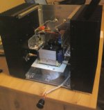
There's been some progress...
Wow a monster, you could make 2 amplifiers with those heatsinks! Great job as always
Yes, it's a "bit" on the large side - heatsink dimensions are 200 x 82 x 280 mm. Fins are serrated, 66mm long and the temp. on them raises to 15 degrees Celsius above ambient at 60W dissipation per channel. VFETs' cases are 5 degrees hotter.
I'm not a fan of big, clumsy amps but I wanted this one to be "extra" reliable.
Transformer is hidden, ironclad, below the PSU deck.
Front plate is still in the works.
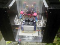
Somewhat clearer image:
I'm not a fan of big, clumsy amps but I wanted this one to be "extra" reliable.
Transformer is hidden, ironclad, below the PSU deck.
Front plate is still in the works.
Somewhat clearer image:
Attachments
- Status
- This old topic is closed. If you want to reopen this topic, contact a moderator using the "Report Post" button.
- Home
- Amplifiers
- Pass Labs
- VFET PP amp