Hi Mcgreg66,
I had hum on my F5. I tried everything, moving wires around, making sure they were twisted, hum busting circuits etc, but what eventually worked was tipping the antek transformer up perpendicular to the amp base.
Then I got the same thing on my Aleph J, built using the same Antek, rotating the transfo didn’t help. So tried replacing my twisted hookup wire for inputs with coaxial cable, Mogami w2330 I think, and that did the trick.
Hifi Porn

Attachments
-
 41CB49EA-955C-42B8-991B-BDEB475C77C1.jpg983.7 KB · Views: 495
 -
 01CDB8D1-2AFD-4B43-A096-5F610843A57C.jpg985.3 KB · Views: 500
 -
 0FABD192-071F-41C1-86F0-A6B91FFF644A.jpg1,008.9 KB · Views: 488
 -
 A88632CD-3B6B-4B91-91D7-544C60EF319D.jpg884.9 KB · Views: 461
 -
 F725F219-5129-433B-9B67-432705C88BE8.jpg890 KB · Views: 246
 -
 78CF40EE-4A24-4C6B-8C0F-F360A363B984.jpg999.6 KB · Views: 422
 -
 D77C6E2A-9B29-4437-AE69-9C7C1C55645C.jpg979.2 KB · Views: 257
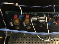
First Aleph J listening tests....make me smile....
....this amp sounds BIG and SWEET...great imaging and focus...
I run it first of all with my 100k passive preamp....
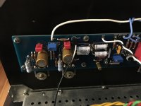
But I have a audible hum on the right channel .....any suggestions how to locate the problem.....?
Thanks all .....Papa Nelson....6L6....ZenMod.....DIY Audio....and all members sharing their ideas, knowledge and passion for no profit!!!
Gregor
have you tried a different pre-amp? different cables? is the chassis grounded?
Hey mcgregg66,
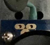
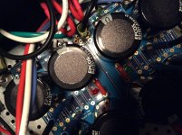
I’m sorry you’ve got the dreaded hum. I’ve been there. I’ve been looking at your pictures on my phone. I’m just throwing this out there and it could just be a weird reflection but I noticed what looks like unsoldered leads coming up through some of the neg rail pads on the PSU. I’m attaching a close up screen grab.
I’m sorry you’ve got the dreaded hum. I’ve been there. I’ve been looking at your pictures on my phone. I’m just throwing this out there and it could just be a weird reflection but I noticed what looks like unsoldered leads coming up through some of the neg rail pads on the PSU. I’m attaching a close up screen grab.
Attachments
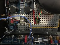
I could be wrong but looks like your star ground is wired incorrectly (only one half is going through the thermistor). Also looks like you have a ground for your transformer shielding; I wired mine to star ground as well
Only PSU ground is connected to star ground via thermistor!
And V+ and V- grounds are connected on board!
http://i198.photobucket.com/albums/aa276/aeroplane_album/F5PSUschematic.jpg
The yellow/green wire is transformer shielding connected to starground!
And mains inlet safety ground goes to starground!
Can’t find anything wrong
Hey mcgregg66,
I’m sorry you’ve got the dreaded hum. I’ve been there. I’ve been looking at your pictures on my phone. I’m just throwing this out there and it could just be a weird reflection but I noticed what looks like unsoldered leads coming up through some of the neg rail pads on the PSU. I’m attaching a close up screen grab.
Thanks but I didn’t used these.....the thermistor is wired under the board to ground...
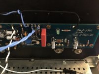
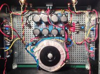
one bigger picture from above, please
are you able to understand schematic of common First Watt PSU ?
I think so.....
Attachments
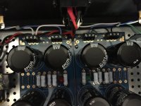
-same color of input wires , be sure that you didn't swap wires between hot and gnd
- you grounded neg input on pcbs ?
-try connecting one fat wire directly between two channel pcbs , their main ground points ........ in other words - bridge two channel gnd points in shortest way possible , to determine is there hum culprit
- you grounded neg input on pcbs ?
-try connecting one fat wire directly between two channel pcbs , their main ground points ........ in other words - bridge two channel gnd points in shortest way possible , to determine is there hum culprit
Much more hum!-same color of input wires , be sure that you didn't swap wires between hot and gnd
Checked again.....alright!
- you grounded neg input on pcbs ?
Yes!
-try connecting one fat wire directly between two channel pcbs , their main ground points ........ in other words - bridge two channel gnd points in shortest way possible , to determine is there hum culprit
Dead quiet!what's situation without nothing connected to input RCAs?
Same hum on both channels!
then with shorted both inputs ?
Only PSU ground is connected to star ground via thermistor!
And V+ and V- grounds are connected on board!
http://i198.photobucket.com/albums/aa276/aeroplane_album/F5PSUschematic.jpg
The yellow/green wire is transformer shielding connected to starground!
And mains inlet safety ground goes to starground!
Can’t find anything wrong
Is it wired underneath?
Nevermind I see that it’s wired underneath but is it connected to the negative rail only? The green wire connected to the thermistor?
Last edited:
Is it wired underneath?
I just put the wire underneath....
....then up to Gnd5
I had a hum problem with my F5 which I finally solved by rotating the transfo. However I got a lot of good suggestions. Here’s the initial post:
http://www.diyaudio.com/forums/pass-labs/121228-f5-power-amplifier-1543.html#post4986983
AndrewT helped me out and gave me some pointers on how to improve my wiring:
http://www.diyaudio.com/forums/pass-labs/121228-f5-power-amplifier-1548.html#post5000555
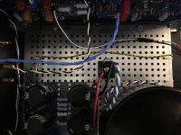
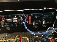
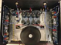
Also, per Andrew again, I always ground my transfo shield as close to the transfo as possible, shortest possible wire. Seems to work. You can see it, a purple wire to the right of the transfo, in the attached image.
http://www.diyaudio.com/forums/pass-labs/121228-f5-power-amplifier-1543.html#post4986983
AndrewT helped me out and gave me some pointers on how to improve my wiring:
http://www.diyaudio.com/forums/pass-labs/121228-f5-power-amplifier-1548.html#post5000555
Also, per Andrew again, I always ground my transfo shield as close to the transfo as possible, shortest possible wire. Seems to work. You can see it, a purple wire to the right of the transfo, in the attached image.
Attachments
Dead quiet!
now , plug in interconnects , connect two RCA gnds on other (free) end of interconnects , power on ;
what's happening ?
- Home
- Amplifiers
- Pass Labs
- Aleph J illustrated build guide