Whaleaman,
How are you connected with Cathedral Speakers? They have a great web site. I am very interested in replacing my pre-amp and they have two options that I am interested in.
Have fun with your Aleph J. I built one this past Spring and am in the process of another. 6L6 is the MAN!
Thanks for your interest, I am responsible for it. Those preamps have been superseded by a current-feedback preamp that some very smart people here helped me design, look towards the end of the National Op Amp inflation thread, pics and all there. The Aleph J is intended to mate with it. Those Cathedral speakers are my brew, they do very well. PM if you got further questions.
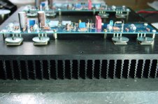
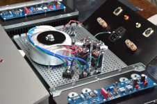
Here is the progress so far on the J, added a pilot light in the front. Wow, that 10MM thick faceplate gave me a workout to drill.
Attachments

Last edited:
Sides on then the front. Then slid the bottom shelf on from the back to the front. Not a chance of it sliding down from the top once components were on. Then bottom cover with rubber feet. BTW, for those with Home Depot, the screws that hold down the transistors are M3 10MM in length. They are in the slide-out drawers with metric nuts and bolts. The washers are #8 1 inch diameter. This is a precisely cut chassis and well worth the money.
Had to stop here tonight...pics.
Had to stop here tonight...pics.
Attachments
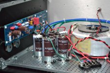
I like the big caps with clamps -- where did you get them?
Those are from Mouser, I will get you the part numbers is a bit.
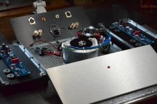
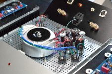
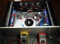
Thought I'd be enjoying the amp by now. Here is where I left off. Finished the amp, got it all wired right. Good voltages.
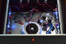
Went to set BIAS, got one side done, went to the other. Then went to adjust offset, left channel 12 volts! Right channel OK, got it down to zero. Went back to left channel, it dialed down way passed zero and back up to -18 volts! This went on for a bit and now it is at full rail voltage, matter of fact just about anything there is reading positive rail voltage. Also went back to measure BIAS and there is nothing there, 0 Volts. This is only the left channel. Other channel is working great.
The lights on the amp are pretty though.

Attachments
Last edited:
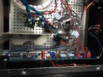
I found the start of my problems, I cut R4 when attaching wiring and did not notice it. Fixed now and I replaced Q2, Q3, Q4. But still getting pos rail voltage at the gate of Q1B and obviously at the outputs. BIAS is 0. Output transistors are cold. Warm on the other channel as they should. So I am thinking Q5 and Q6 are blown since they run off of the positive rail? Q1B runs off of the negative rail no? I have a couple spares.`
Attachments
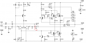
recheck all solder joints
cut R4 couldn't result in blown outputs , as long you didn't connect load
Thanks, no load connected. So maybe safe. I could use a pair of Linear Systems LSJ74 if anyone has a pair to sell in the US.
I like the big caps with clamps -- where did you get them?
These are from Mouser, yes they are nice. Click on the link for the part #:
Caps link
Clamp link
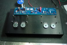
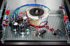
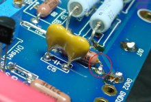
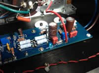
This picture tells it all. Everything works fine now, the offset pot was all the way in down to zero. Once backed out, voltage came down.
BIAS at .400 of a volt. Nice! Hook up later...
Attachments
I was expecting the caps to be bigger than 35mm... Those would fit on the diyAudio PSU board...
Still, I like the clamps.
Yes, they kind of make it look business like.
OK, this thing sounds as good as you'll said or better! Toll!
I do have very very faint hum in the right channel, power type hum, not the signal ground hum type. So I cleaned up the wiring up, but still.
You know, the annoying kind only hear it between songs.
Tell me where to look--not the obvious stuff, done that.
Congratulations, Whaleman. You will truly enjoy your Aleph J.
WRT the trouble that I had (post 996 et. seq.), it was fixed by some excellent guidance here and putting in new Mosfets.
Whaleman, what pre-amp are you going to match up to your Aleph J?
I imagine you are going to use your Cathedrals for speakers.
WRT the trouble that I had (post 996 et. seq.), it was fixed by some excellent guidance here and putting in new Mosfets.
Whaleman, what pre-amp are you going to match up to your Aleph J?
I imagine you are going to use your Cathedrals for speakers.
Take the bolt out of the transformer and rest it on it's edge. See if the hum remains.
As Nelson says, it's the big elephant in the room.
BTW, I can't see it in the photos, where did you connect the purple shield wire?
That is my plan for later since the hum is only in the channel closest to the rectifiers.
The purple wire is connected to the chassis, almost under the transformer.
Congratulations, Whaleman. You will truly enjoy your Aleph J.
WRT the trouble that I had (post 996 et. seq.), it was fixed by some excellent guidance here and putting in new Mosfets.
Whaleman, what pre-amp are you going to match up to your Aleph J?
I imagine you are going to use your Cathedrals for speakers.
I hope to use that LME49713 based pre amp since it has the XLR out. Think I am eventually going to put that on a PCB design, but been moving into other projects too quickly with very little time. You can try it with the info on that thread, but it was very hard to get right, many nights and questions.
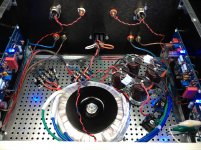
Hi whaleman, Hi, try to minimize the area between the wires of the transformer and the bridge rectifier.
If so it will not go, try moving the two rectifier bridges in to center of the chassis ( maximum distance between the high surge currents and input circuits ).
Thanks, going to try that. I may even braid the secondary wires as well. May also have a shield I can add in front of the input area of the board. The other channel is dead quiet.
Moved the rectifier bridges right next to the toroidal, installed an aluminum shield, moved wires away from each other. No change.
Only on right channel.
Hint:
Nothing connected except speakers, you put your ear to the speaker and can hear the hum.
Connect preamp, hum becomes very noticeable in that channel.
Take interconnect off and short channel out, same hum as if pre is connected. (shorting channel does not quiet things down but makes it louder).
Connect chassis to signal ground, hum becomes noticeable.
Toroidal will be removed next, maybe run on battery
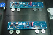
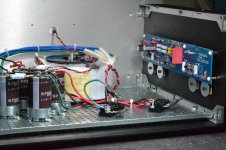
Spent 3 hours to arrive at the same exact place, with faint hum in the right channel. You can see in the pics how the wire and shield look.
Me thinks I need to remove the board a second time and measure every single resistor, even if I have to lift one end up.
Already checked every solder connection when I had it out.
Me thinks I need to remove the board a second time and measure every single resistor, even if I have to lift one end up.
Already checked every solder connection when I had it out.
Attachments
- Home
- Amplifiers
- Pass Labs
- Aleph J illustrated build guide