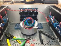
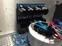
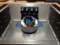
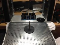
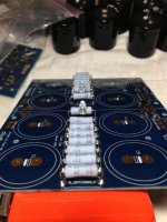
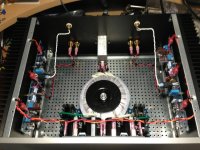
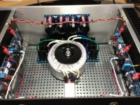
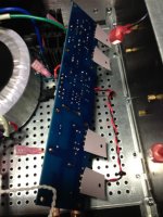
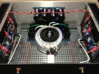
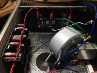
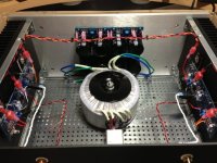
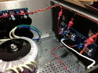
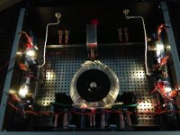
Here are the photos of my F5/Aleph J build:
Attachments
-
 IMG_0322.jpg66.8 KB · Views: 2,540
 -
 IMG_0333.jpg109.2 KB · Views: 1,176
 -
 IMG_0331.jpg107.9 KB · Views: 1,102
 -
 IMG_0330.jpg83.2 KB · Views: 1,148
 -
 IMG_0329.jpg122 KB · Views: 1,364
 -
 IMG_0327.jpg100.5 KB · Views: 1,339
 -
 IMG_0326.jpg109.9 KB · Views: 3,412
 -
 IMG_0325.jpg116.5 KB · Views: 2,292
 -
 IMG_0324.jpg93.6 KB · Views: 2,298
 -
 IMG_0323.jpg91.2 KB · Views: 2,325
Continued:
Attachments
-
 IMG_0351.jpg113.6 KB · Views: 1,137
 -
 IMG_0350.jpg126.7 KB · Views: 919
 -
 IMG_0348.jpg96.7 KB · Views: 861
 -
 IMG_0347.jpg106.1 KB · Views: 835
 -
 IMG_0346.jpg107.5 KB · Views: 869
 -
 IMG_0343.jpg115.1 KB · Views: 852
 -
 IMG_0338.jpg114 KB · Views: 796
 -
 IMG_0336.jpg103.4 KB · Views: 804
 -
 IMG_0335.jpg114.7 KB · Views: 811
 -
 IMG_0334.jpg112.2 KB · Views: 1,056
Hi Henry,
I can't see the pics that 6L6 posted -- I truly am blind as in no light perception in either eye so I'm totally dependent on descriptions.
Thanks,
Jim
Not too worry. Jim explained your situation in a PM to me. I believe Jim will come and visit you. If you still need some guidance though, I will try to explain as best I could.


Aleph J Setup
I just completed one channel.....it did not blow up or smoke, however I am not showing any voltage on the source resister. I noticed that R27 is used to adjust the bias....I have that jumped and the variables are on R7 and R8. I am very confused. I have seen many different stuffed boards and I am not sure If mine is correct. I have 12 volts on the output and the pot does nothing. Thanks for any help. Allan
I just completed one channel.....it did not blow up or smoke, however I am not showing any voltage on the source resister. I noticed that R27 is used to adjust the bias....I have that jumped and the variables are on R7 and R8. I am very confused. I have seen many different stuffed boards and I am not sure If mine is correct. I have 12 volts on the output and the pot does nothing. Thanks for any help. Allan
R8 probably should just be a fixed 1K resistor (no pot) for simplicity, same as the original Aleph J. R7 will set your output offset and needs to be a 2K pot, set for halfway before installation as a starting point. Looking at the latest schematic included with the BOM, R27A is a jumper, and I would use a 100K pot at R27, set for 68k. Look at the schematic if anything is unclear. If everything is installed correctly, and the parts are good, adjusting R7 will allow you to quickly set the output offset at 0 volts.
Last edited:
Do you think that includes the aleph-x series? I took a break from the hobby when everyone was building x amps. I came back and everyone seemed to have abandoned them and were/are building F4, F5...
I just completed one channel.....it did not blow up or smoke, however I am not showing any voltage on the source resister. I noticed that R27 is used to adjust the bias....I have that jumped and the variables are on R7 and R8. I am very confused. I have seen many different stuffed boards and I am not sure If mine is correct. I have 12 volts on the output and the pot does nothing. Thanks for any help. Allan
R8 adjusts the bias of the input Jfets only.
R7 adjusts output DC offset.
R27 sets the gain of the Aleph CCS, and in doing also sets the bias of the output transistors.
12V offset seems like way too much, however. Double check your soldering, replace the pot on R8 with a 1K resistor.
Take lots of well-lit, in-focus photos and please post them here, maybe it's something else and we can see it.
Last edited:
Do you think that includes the aleph-x series? I took a break from the hobby when everyone was building x amps. I came back and everyone seemed to have abandoned them and were/are building F4, F5...
yup
eeny weeeny Jfet FE is , as it seems , contributing to mellow THD spectra
Pa knows his drek , how to please customers
bull' the bull'ers

Aleph J Setup
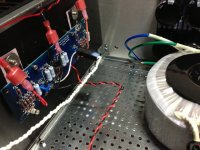
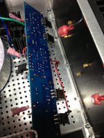
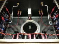
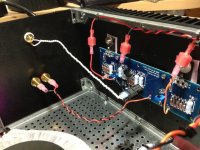
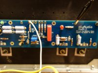
I made the change to R17 and the 1K to R8. There still is no voltage at the source resitor. There is 2.5 volts at R8. The output voltage is still 12 volts. Enclosed are sme photos. Thanks
I made the change to R17 and the 1K to R8. There still is no voltage at the source resitor. There is 2.5 volts at R8. The output voltage is still 12 volts. Enclosed are sme photos. Thanks
Attachments
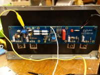
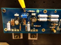
Well Q7 and Q8 are not being turned on yet because you've got to get ~4.5V or so on the gates of those guys before any current flows. Have to get the LTP sorted out first, meaning ~8.5mA of current through there. Voltage across R7 all depends on the amount of current through it.
Couple of observations, I don't like the alligator clips hooked up that way. What I do is solder a short piece of bus wire right there... to clip to instead. And those inputs are probably not happy floating like that. Solder a short little jumper between (-) and ground, assuming you'll run the (+) to your RCA jack. Do you get 9.1V across zener D1? And people always struggle with getting genuine jfets for the front end, that's always a concern. Where did you obtain yours?
Couple of observations, I don't like the alligator clips hooked up that way. What I do is solder a short piece of bus wire right there... to clip to instead. And those inputs are probably not happy floating like that. Solder a short little jumper between (-) and ground, assuming you'll run the (+) to your RCA jack. Do you get 9.1V across zener D1? And people always struggle with getting genuine jfets for the front end, that's always a concern. Where did you obtain yours?
I made the change to R17 and the 1K to R8. There still is no voltage at the source resitor. There is 2.5 volts at R8. The output voltage is still 12 volts. Enclosed are sme photos. Thanks
Sounds like you may have damaged the jfets since the front end CCS is only delivering 2.5 mA. Any spares? What is the voltage across R7?
- Home
- Amplifiers
- Pass Labs
- Aleph J illustrated build guide