Mount the PCB and the mosfets to the heatsinks without bending anything, take a look at the distance from the side, and determine where the bend needs to be.
Then take the mosfets off, and bent them over a widget of some kind (metal or wood block, etc...) at that distance. You need to be in the ballpark, but not precise to the micron, there is more wiggle room that you might think.
Then take the mosfets off, and bent them over a widget of some kind (metal or wood block, etc...) at that distance. You need to be in the ballpark, but not precise to the micron, there is more wiggle room that you might think.
There is a nice method shown in the ACA instructions. Basically, temporarily bolt the MOSFET in place, then put the board over it in its location. Once you find the spot on the MOSFET leg, repeat for the others. Then, after the board is fully stuffed, bolt down the mosfets for real, bolt down the board, then solder the MOSFET legs to the board.
Totally not my idea, and it worked great on the ACA.
Edit-errr, what he said
Totally not my idea, and it worked great on the ACA.
Edit-errr, what he said
The bend ends up being where the skinny part of the MOSFET lead meets the fat part with the skinny part doing the bending (skinny vertical, fat horizontal). That was a nice touch by Didiet. An easy way to start the bend is insert the MOSFET all the way in to one of the board through hole positions and just bend it over the board about 30º. Use 6L6's widget method or a steady hand with needle nose pliers to finish the bend.
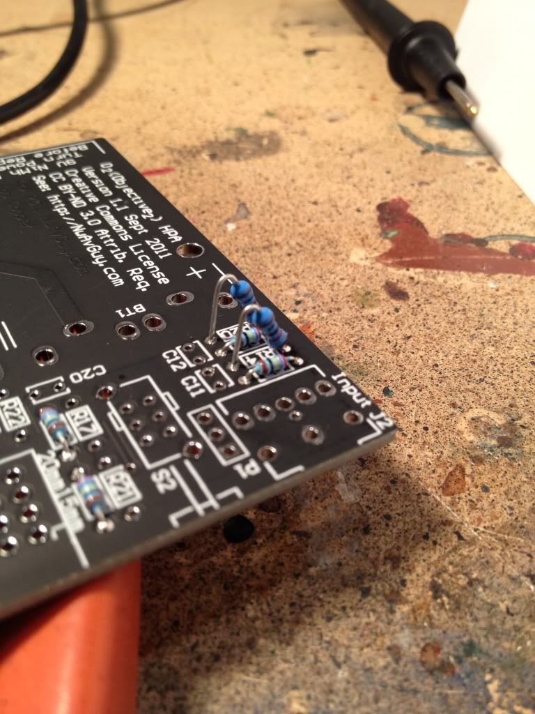
The bigger resistors are mounted soldier-style.
(I thought soldier style was the real term for that... maybe not...)
That is how I have always heard it referred to....soldier style. Had to do it plenty on the Peter Daniels F-5 board...they are slightly smaller than a business card!
Russellc
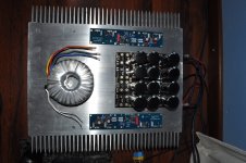
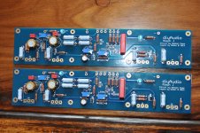
Here I have taken a picture where I am checking my spacing and layout against my KSA50 to get an idea of the sizing for my case. I will take a more close-up pic later today.
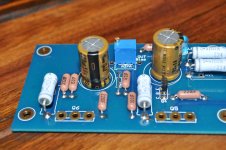
Note that I have used the smaller in size Nichicon FG caps. I am saving money for my heatsinks for next month. They will be the same as those I have used for my KSA50. Maybe just a tad smaller in lenght and height. Same profile though. They are working very well on my KSA50.
Note that I have used the smaller in size Nichicon FG caps. I am saving money for my heatsinks for next month. They will be the same as those I have used for my KSA50. Maybe just a tad smaller in lenght and height. Same profile though. They are working very well on my KSA50.
Attachments
A couple of questions related to the build that I can't seem to find answers to:
The mounting hardware for the board and FETs is m3, but how tall should the standoffs be (this is my first Pass build).
2) I see that in the spec sheet for the Keratherm insulators there is a torque specification but with my screen reader software it is nearly impossible to figure out what data goes with what label in tables -- could somebody look this up and post it for me? I'm blind so can't read things in the normal way.
3) is there a description of the locations of holes for the UMS, and how high off the bottom of the heatsink should the bottom row off FETS go? The heatsinks are Conrad mf35-151/.5.
Any other tips on mounting the boards and FETs? I'm experienced with tapping blind holes but picked up some extra m3 bottom taps just in case.
I'll have to get somebody local to show me where the various power, ground, in and output connections on the board are so I can layout the chassis, but that can wait until the heatsinks are machined.
Thanks,
Jim
A couple of questions related to the build that I can't seem to find answers to:
The mounting hardware for the board and FETs is m3, but how tall should the standoffs be (this is my first Pass build).
2) I see that in the spec sheet for the Keratherm insulators there is a torque specification but with my screen reader software it is nearly impossible to figure out what data goes with what label in tables -- could somebody look this up and post it for me? I'm blind so can't read things in the normal way.
3) is there a description of the locations of holes for the UMS, and how high off the bottom of the heatsink should the bottom row off FETS go? The heatsinks are Conrad mf35-151/.5.
Any other tips on mounting the boards and FETs? I'm experienced with tapping blind holes but picked up some extra m3 bottom taps just in case.
I'll have to get somebody local to show me where the various power, ground, in and output connections on the board are so I can layout the chassis, but that can wait until the heatsinks are machined.
Thanks,
Jim
1. I use the 8mm stand-offs when mounting a board to a heatsink
3. I usually make that at between 35% and 40% of the height of the heatsink when mounting one row of FETs. When the board calls for 2 rows, top and bottom this will have to be adapted to take the width of the board into consideration.
Henry,
Thanks -- so the FETs are outside the edges of the board then? Somehow from another post I got thee idea that they were tucked under the board which I thought a little odd. That's good to know. I can go from there on the FET and board positioning so the heatsink gets used as fully as it can.
Thanks,
Jim
Henry,
Thanks -- so the FETs are outside the edges of the board then? Somehow from another post I got thee idea that they were tucked under the board which I thought a little odd. That's good to know. I can go from there on the FET and board positioning so the heatsink gets used as fully as it can.
Thanks,
Jim
Yes, if you look at post #1 and #2 of Jim's excellent build guide (this here thread), you will see how the FETs should be mounted. Note that with the UMS that the FETs are actually mounted lower than my 35%-40% rule. That is purely to compensate for FETs that may be mounted on the top also on other DIY Audio designs.
However, if you are going to drill your own holes and if you are only going to use the AJ (or F4) on the sink you may make use of your sink more efficiently and mount the board higher sothat your FETs align on the 35%-40% line.
Sorry I typed, F5 when it should have been F4.
LOL, heck no......still trying to get all the parts through front door for F4 without being caught by wife")
Odd isnt it? I keep calling aleph j "F-6" for some dam reason...sorry Jim (6L6)!
Russellc
Well I've got one channel running in my workshop, sounds great. Lots of gain, no hum or noise, output offset is well behaved. My output stage is Babelfish J inspired since I had a small pile of IRFP150's salvaged from the scrap heap at work. Didn't stuff the current limiter parts. Grounded the (+) input, I'm using the (-) input with a chunky boutique 2uF film cap at the RCA jack. I had a tightly matched quad of J74's (10mA idss) I was saving for something special like this. After a few hours of run-in, idle current is 1.85A (started about 2A). No problem for my heatsink, could dial this up some more. Hopefully monoblock number two will come up as smoothly as this one did...
- Home
- Amplifiers
- Pass Labs
- Aleph J illustrated build guide