Aleph J board error - alternative resistor placement
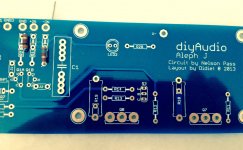
...or is it me? I bought the (2013 layout) boards from the diyaudiostore in Dec and have been accumulating parts, etc since. Last night I rough-filled one board and thought I was near to powering up when I tested resistance from input to ground (rca / single ended) and it was open. ??? said I. In the attached photo, I've put two allen bradley 1/4 watt Rs in alternative positions where Rs 2 & 3 go. The silkscreen for R1 is the same. Last night, the spacing and graphic led me to solder up the R3 alternative. In fact, the R2 alternative works (with kinda useless awkward spacing) and the R3 alternative (which is sized correctly) leaves the resistor shorted across itself. Same applies for the R18 alternative mounting(s) on the right side of the photo (and its kinfolk). So I'm desoldering eleven components. Has this not come up before / does everyone use large format resistors?
...or is it me? I bought the (2013 layout) boards from the diyaudiostore in Dec and have been accumulating parts, etc since. Last night I rough-filled one board and thought I was near to powering up when I tested resistance from input to ground (rca / single ended) and it was open. ??? said I. In the attached photo, I've put two allen bradley 1/4 watt Rs in alternative positions where Rs 2 & 3 go. The silkscreen for R1 is the same. Last night, the spacing and graphic led me to solder up the R3 alternative. In fact, the R2 alternative works (with kinda useless awkward spacing) and the R3 alternative (which is sized correctly) leaves the resistor shorted across itself. Same applies for the R18 alternative mounting(s) on the right side of the photo (and its kinfolk). So I'm desoldering eleven components. Has this not come up before / does everyone use large format resistors?
Attachments
One PSU works beautifully.
Dial mono in a single case isn’t worth the bother in my opinion, make monoblocks for actual benefit.

Single PSU does work beautifully.
Dual mono in a single case was, however, very well worth the effort for my Aleph J.
You've got me thinking, though.

Does the additional shielding (including air gap?) between channels provided by the separate chassis, help give the "actual benefit" you mention?
...or is it me? I bought the (2013 layout) boards from the diyaudiostore in Dec and have been accumulating parts, etc since. Last night I rough-filled one board and thought I was near to powering up when I tested resistance from input to ground (rca / single ended) and it was open. ??? said I. In the attached photo, I've put two allen bradley 1/4 watt Rs in alternative positions where Rs 2 & 3 go. The silkscreen for R1 is the same. Last night, the spacing and graphic led me to solder up the R3 alternative. In fact, the R2 alternative works (with kinda useless awkward spacing) and the R3 alternative (which is sized correctly) leaves the resistor shorted across itself. Same applies for the R18 alternative mounting(s) on the right side of the photo (and its kinfolk). So I'm desoldering eleven components. Has this not come up before / does everyone use large format resistors?
Always best to check the track traces on the board first.
Hi Jim,
Thanks for that, good to see you in this thread again and thank you for all of your work with this project, and other projects as well.
Well that's a good thing as I just started to layout the bottom and there is no way to get all the caps for dual xfmrs in there, it will be a challenge to get 8 in there.Now that I am thinking about it, the 5A xfmr actually would be enough for both channels as each channel only draws ~1.7A DC. I also have a plethora of dual 24VAC @ 8A dual winding torroids as well, but that would cause excessive heat in the amp. I think I might save the big 10A torroids for my F5T build.
Anyway, thank you again.
Cheers
Shoot, build your amp with single power supply. Later, buy another identical case and power supply. Pick another Amp, say M2 buy boards from store and stuff them.
Then, move one of the channels of your AlephJ to it, and put one of the two new boards for M2 ( or other Papa amp) one into each case. With DPDT switch to move power supply between different boards, you now have Aleph J mono blocks, and with flip of switch (while powered down) you have M2 or whatever amp also in mono blocks.
You will have two different amps in mono blocks, and can enjoy your single power supply Aleph J for now.
Just got my switches delivered to try this conversion, there is a thread here somewhere another member wrote.
Russellc
That idea has been bouncing around in my head for a month or two now.
So, could the INs and OUTs of two boards remain hard wired in parallel, or would these quantities have to be switched as well?
Please post the thread you mentioned if you recall it.
Shortage of coin to do 2 separate cases, and a reluctance to touch my AJ (as it is working s-o-o well in its 5U) if going single chassis are among my hold ups, but I betcha I get to some version of it eventually.
I have PCBs and all parts to do the M2x and ZM's SissySIT boards which have been sitting around too long.
They really deserve a chance to sing.
Original plan was to swap boards in and out of the 5U, but I'm beginning to think a set of monoblocks for the other amp boards may be the way to go if I can swing it so the AJ can be left well enough alone.
I think this might be the thread Russelc mentioned: I turned my two stereo amps into mono-blocks for 10 dollars
Also, thanks for all the input on power up from those of you that have posted. I had to leave it for the evening, so only got one channel biased with full power. So far so good. I haven't tried playing music yet. The weekend can't come fast enough!
Here's an electronics newbie question: Without the Aleph PCB connected to the PSU, I was getting 25v on the rails. Once I connected the PCB, though, I couldn't get a voltage reading from the PSU rails. This was freaking me out for a while until I disconnected the PCB and measured the PSU voltage again and again got 25v. Is this normal? Or am I measuring the PSU incorrectly? I assumed that the voltage at that given point in the circuitry would remain consistent regardless of whether the amp PCB was hooked up... but that assumption appears to be wrong.
Last edited:
Moving along nicely
One side is done (except for a few straggler parts coming in Monday) and I decided to order the right 0R47 resistors and a couple of the bypass caps that I would have been compromising quality on as I only have MMK types in the size required, although I see MMK Evox actually get pretty good reviews here on DIY.
I think I may point to point the power supply, mounting the quad of diodes on old fashioned terminal strips (like in tube amps), need to figure out how much heat sink will be required for each and install those, layout the bottom panel and wire it all up. I could test this weekend as all of the critical parts are on the boards.
I'll keep you posted.
A few pictures of Muppet Labs attached.
Cheers
One side is done (except for a few straggler parts coming in Monday) and I decided to order the right 0R47 resistors and a couple of the bypass caps that I would have been compromising quality on as I only have MMK types in the size required, although I see MMK Evox actually get pretty good reviews here on DIY.
I think I may point to point the power supply, mounting the quad of diodes on old fashioned terminal strips (like in tube amps
), need to figure out how much heat sink will be required for each and install those, layout the bottom panel and wire it all up. I could test this weekend as all of the critical parts are on the boards. I'll keep you posted.
A few pictures of Muppet Labs attached.
Cheers
Attachments
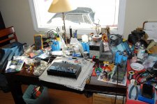
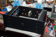
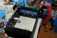
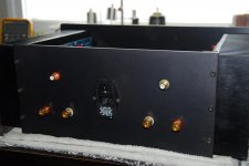
A few more pictures
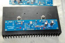
And here it is assembled and ready for power supply mock up. Lots of room for 8 capacitors and a xfmr, 8 TO-220 diodes with heat sinks, and 16 resistors. As I am using single IRFP150s I am using 0R27 source resistors, but I will use 4 of the 0R47 for R20-R23 which will be here Monday, but this weekend I will at least be able to power it up and get it close to dialed in. I still need to drill the holes for the XLR jacks as back in 1993 when I built these chassis, I wasn't using XLRs.
When I do the final assembly I am going to use a little thermal grease between the front-back panels and the heat sinks, for a little extra dissipation.
Cheers
Attachments
Last edited:
Grazie
Yes, that is the thread and has better explanation than I could give. Ins and outs as well as grounds remain as is, just power supply lines switch from one board to the other.
I believe one of the advantages discussed was less ground loop troubles and hum free operation. Looks neato as well.
Russellc
It's alive...it's alive
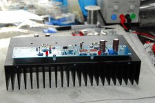
Rigged up a simple single section power supply and powered up one channel successfully, set the bias and offset (which was very close to begin with) and set the idle current to 1.85A total, .5VDC across the 0R27 source R and let it run for 20 minutes or so, monitoring the temps all along. It eventually hit 58*C on the fins and the plastic case of the IRFP150 was 80*C so I backed off idle current to 1.6A and it seemed to stabilize around 55*C on the fins and 78*C on the device. This is all with the channel just standing by itself on a couple of large Allen wrenches to keep it off the bench, I think I will be able to turn up the idle current when I assemble all the chassis and have that extra mass to help dissipate the heat. PS voltage is +/- 25VDC. I could also just leave it as is, as my speakers are Big Reds with Altec 16 ohm 604E2 drivers and 20 watts will be plenty.
Another thing I wanted to say was that there was mention of wire size earlier in the thread, I want to confirm that even my little simple test setup with 18ga wire, there is virtually no voltage drop across 1.5' of wire so I am going to wire this amp with it as it is very nice Teflon coated silver plated stranded wire and the runs from the caps to the board will be short anyway.
That's it for now.
Cheers
PS I just looked at the data sheet again for the IRFP150 and it states even at 100*C case temp it will handle 30A and will dissipate 160 Watts. Am I babying this device too much and should I crank it up a bit? Thanks
Last edited:
I have now assembled both channels and all panels except top/bottom are installed, I'm warming it up now with 1.85A per channel, we'll see how it goes. The 35A bridge is getting very hot, even with a heat sink.
I noticed a HUGE difference in the power supply behavior when I connected the second channel and wanted to pass it along for those who may be having some hum problems. For this test setup I am just using a pair of 27,000uF caps and a 35A bridge with the 20-20VAC 8A xfmr, it's not C-R-C, just C.
First observation with just one channel operating, both audio inputs just open, actually I don't even have the 1uF cap in yet, nothing grounded, just open inputs and I thought I would check the output for hum, well I was completely amazed, it was absolutely ZERO, no millivolts, nada, nothing. WOW! Amazing. I checked the power supply and it had 100mV ripple. Cool, okay this is going great. Then I connected the second channel and I checked the output again and now there is almost a full volt of AC on the speaker outputs, and there is now 200mV ripple on the PS caps, wow! What a difference.
Anyway, the loading of the bridge and capacitors really has an effect on the ripple, so when I build the final PS, I will be using a pair of 27,000uF and a pair of 15,000uF with the R47 resistors in between, as well as double bridge rectifiers using individual high speed soft recovery diodes. Hopefully that will keep the ripple and hum at zero on the output.
I'm going to try double bridges now just to see if the ripple goes away.
More Later.
Thanks EB for letting me about those posts, I read them and I will implement the change when I pull the boards out to finish stuffing them. I think my current hum issue is to do with the fact that I only have 4 caps in the PS, connected with clip leads, not much ripple will get filtered with 20ga clip leads.
The amp has now been operating for 3 hours and seems to have stabilized at 1.85A, 24VDC rails, AC power monitor indicates 1.78A draw and 204W, and heat sinks are 55*C and front and rear panels are both 45*C, so they seem to be helping with the dissipation. Room temp 25*C so I think this is the happy spot for the amp.
I'll start working on the final PS tomorrow and hopefully have the amp finished this week.
Cheers
The choice of rectifiers makes a difference in a high current amp like the Aleph J. If you are using the common GBPC3504 or similar, they drop a lot of voltage at constant current, and therefore dissipate a few Watts of power. Rectifiers with a lower forward voltage drop will dissipate less power. The Vishay VS-26MB40A rectifiers are a good substitute for the block style, and will drop less voltage. My Aleph J uses a CRCRC PSU board with 27,000 uF caps in each position and a set of LVB2560 inline rectifiers. My bias current is set around 1.8A total per rail. Those rectifiers run hot with the heatsinks I'm using, but they drop less voltage that way, and make a good sounding amp. I leave it on 24hrs a day whenever it's in the current rotation.
Check out 2 picoDumbs PSU implementation at On A Hippie Trail, Head Full Of Zombie for an alternative big block rectifier.
Check out 2 picoDumbs PSU implementation at On A Hippie Trail, Head Full Of Zombie for an alternative big block rectifier.
Last edited:
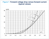
If your PSU design accommodates individual TO-220 rectifiers with 3 legs, as for example the Universal Power Supply PCB in the diyAudio store does, then the Field Effect Rectifiers from ST Microelectronics are appealing. Their forward voltage drop is amazingly low, thus they dissipate far less power and require less heatsinking. Have a look at their Vfwd at 25 amperes. Amazing!
_
_
Attachments
- Home
- Amplifiers
- Pass Labs
- Aleph J illustrated build guide