The 12v bipolar power supply is what I have here ready for action. I have the DIY pcb for the PS but not the associated parts. just wondering if 12v will make noise.
For a couple of bucks, you could try bumping up the voltage and see if it works:
150W 10A 10V-32V to 12V-35V DC-DC Boost Converter Step Up Power Supply Module 664469125966 | eBay
Post: Aleph J illustrated build guide~~~~~~~~~~~~~~~~~~~
Aleph J chassis guide
This guide shows some construction of photos using the DIYaudio store 5U "Big Amp Chassis" with the additional bag of hardware.
The 4U Chassis will also be appropriate for this amp.
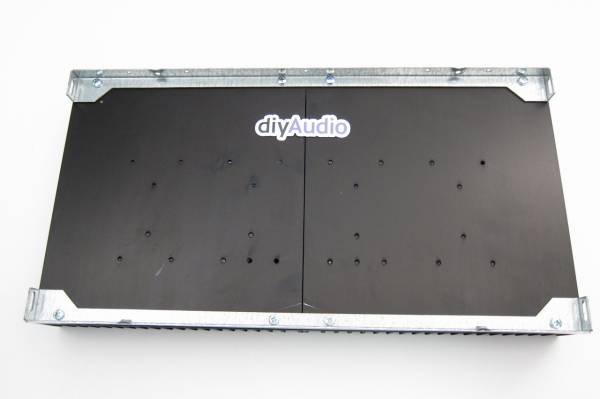
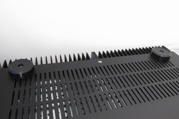
The best place to begin is assembly of the heatsinks, which also form the sides of the enclosure. In this photo you can see the galvanized brackets that the black anodized heatsinks will bolt into.
The 5U heatsinks are 2-piece per side, the 4U are a single extrusion.
The UMS bolt pattern is clearly visible.
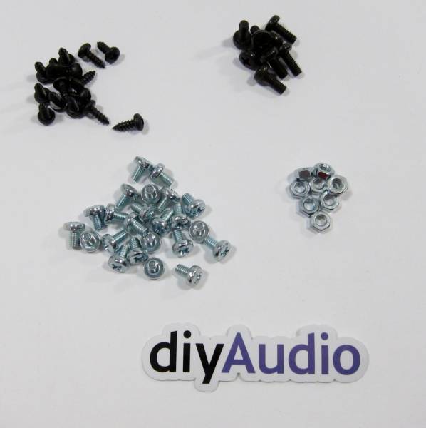
This is the hardware to assemble the amp.
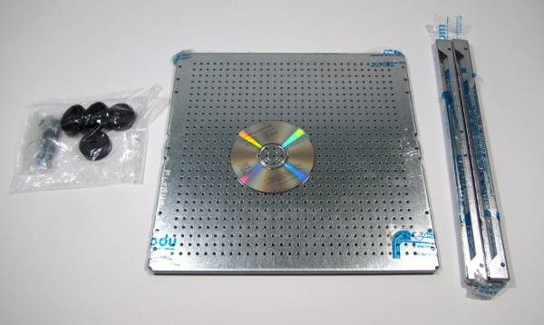
This build utilizes the "DIY-friendly perforated base plate" shown here with the original packaging of the heatsink brackets and the chassis feet.
The Deluxe chassis back panel, and the chassis faceplate.
The back panel parts kit, includes PCB mounting hardware. (optional)
This shows the contents of the hardware pack from the Back Panel parts Kit.
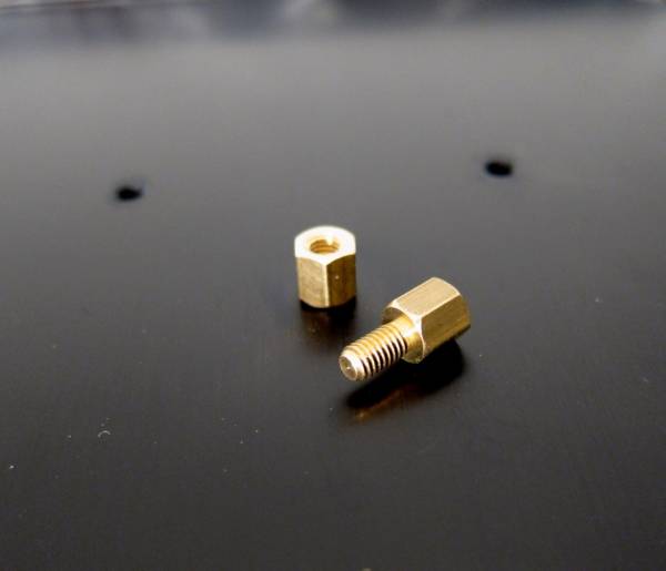
PCB standoffs.
These may be too short for the Aleph J depending on what output transistors you use, I had no problem with the Fairchild Mosfets, but the IRF might be too thick, requiring the simple fix of using slightly taller hardware.
I haven't used the IRF first-hand and cannot verify that there is or is not an issue. Again the fix is very easy. (All the threads are M3)
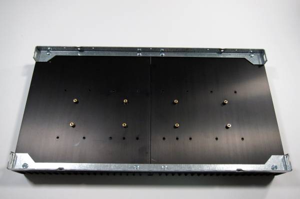
Mount standoffs as shown.
The heatsink sides mount to the chassis bottom. (Not shown)
The Perforated baseplate mounts on top of the regular bottom, with the bent edge facing down. You may need taller hardware - I did. (This same screw mounts the feet to the chassis)
This is the hardware for the IEC inlet.
Mount as shown.
Speaker post inside.
Speaker post outside.
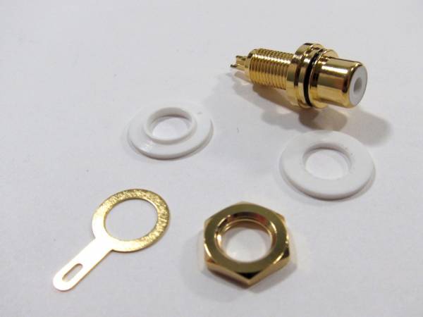
All the components of the RCA jack. Note the lip on one of the washers, this goes inside the hole to keep the metal from touching.
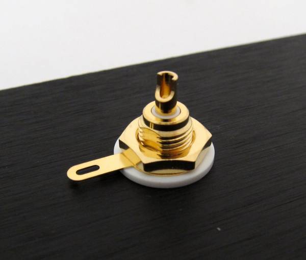
Also note the ground lug does not touch the metal, but is insulated by the washers.
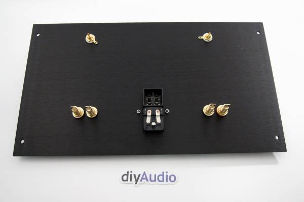
Completed back inside.
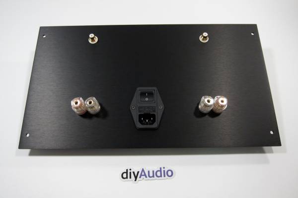
Outside.
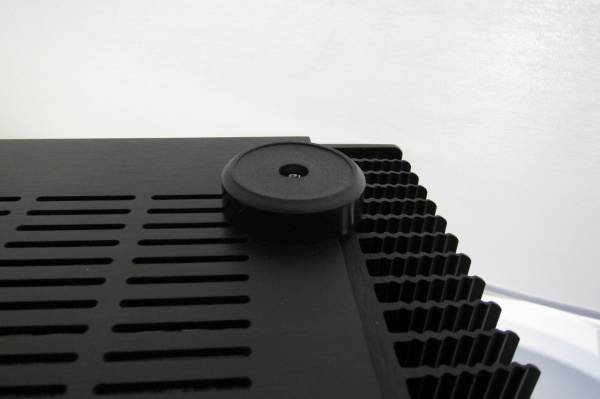
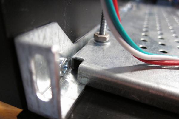
The Feet mount to the Chassis on the same bolt that secures the Heatsink bracket to the chassis bottom.
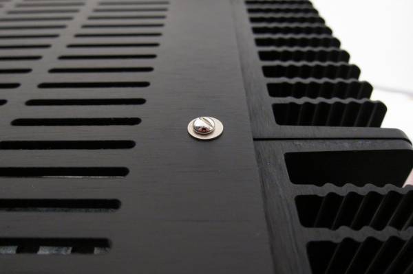
Bottom middle screw.
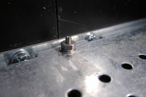
Middle screw inside, I used different hardware again, I wanted a bit more girth and some washers.
Both bottom edges should look like this when done.
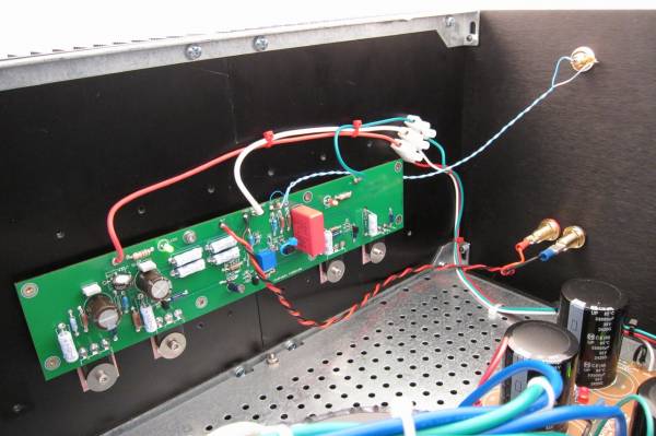
This photo shows (behind all the various wires, sorry…) the mounting of the heatsink brackets to the heatsinks themselves, the back and the bottom.

Back panel in use.
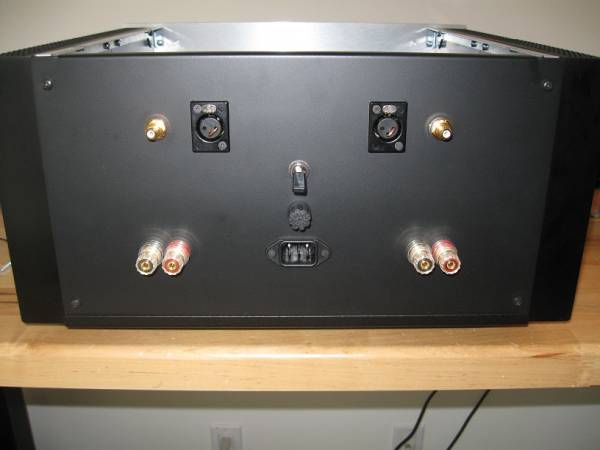
This photo is of Grimberg's Aleph J, he used a chassis with the blank rear, and drilled himself. Obviously the XLR jacks are different, as well as the use of individual IEC, fuseholder, and power switch instead of the power entry module. It looks great!!
Grimberg's back panel interior. Very nice!
Forum: Pass Labs
Assigned Moderators: N/A
Posted by: 6L6
Original Content:[/QUOTE]
Aleph J is the total negative feedback, the magnification is only 1, how can reach 25w power?
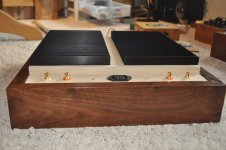
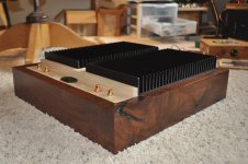
I was on a roll for a while building bases just for practice using wood from a tree we had cut down on our property. I modified this a bit to work. Light colored wood is White Oak.
Can use a heatsink for a grounding point?
Can use a heatsink for a grounding point?
Attachments
Pass DIY Addict
Joined 2000
Paid Member
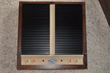
") Do you have a way to measure the temp of your sinks? This is less than optimal orientation and I'm curious what kind of temps it produces.
Do you have a way to measure the temp of your sinks? This is less than optimal orientation and I'm curious what kind of temps it produces.That IEC power socket looks dangerous - the connecting power cord would need exposed power pins. Fortunately standard power cords do not have exposed power pins and would not fit that socket.
That's going in the trash. I see where you're coming from. Thanks
The standard substitution is a matched pair of 2sj74 or lsj74. Matched pairs of lsj74 are available at the diyaudio store.
Is there a preferred Idss for J74 pair for Aleph-J? In general, given the spread from 6-12mA are the higher ones more desirable or lower values (not just for AJ) if such a generalization or observation is possible? Thanks!
Thanks 6L6, matching only needs to apply to the channel, they don't need to match left/right is that correct?
Last question - if they were matched at 9V (on battery), how well does that matching hold up as implemented in the AJ? Would it be necessary to match at (what is the voltage?) the voltage it would see in the AJ?
Last question - if they were matched at 9V (on battery), how well does that matching hold up as implemented in the AJ? Would it be necessary to match at (what is the voltage?) the voltage it would see in the AJ?
- Home
- Amplifiers
- Pass Labs
- Aleph J illustrated build guide