Hi, so Iv'e been working on the F5 turbo for a while I did have it running fine but with Hum, i went thru a few diferent Wiring layouts in the past and managed to get the hum very low but then added more capacitors so had to change layout again and the hum came back then one channel blew.
Finaly fixed that and was suggested i get Tea-Bag's PSU boards so did and here I am hoping some can look at my wiring layout to see if im going the right way.
None of the wires on the PSU are soldered yet, diodes not mounted im just trying to get an idea of the wiring layout before i proceeed, im sure im wrong so have posted here how its wired so far.
heres my layout on the Diyaudio boards
Ive wired EXACTLY like this, as u see the grounds are wired together. Which is what ive done...

Layout 1 (all grounds going to the PSU board)
Im only using 1 diode board and 1 PSU for both channels (Shared PSU)

Diode board
Green wires = AC in
DC from diode board to the PSU board (am i using the right end ? since i have only one diode board)

Top view, Ignore the messy parts and difference between channels, im rewiring the right channel at the mo.
So here u see the other end of the PSU board power out + and - which will go to N and P channel boards, then off to the gain stage board.
Am i confusing things by now ? lol
P and N channels grounds connect to the gain stage boards then to the PSU
Alternative idea

Note: the wires wont look like that im just showing my point of central ground point.
Left and right channels GND, transformer center tap , and ground from the ground loop protecting rectifier bridge. all meet at a Central ground point. THEN from there a single wire connects from there to the PSU board.
If this all sounds insane im going to have to tidy up and try to make things more obvious lol
Finaly fixed that and was suggested i get Tea-Bag's PSU boards so did and here I am hoping some can look at my wiring layout to see if im going the right way.
None of the wires on the PSU are soldered yet, diodes not mounted im just trying to get an idea of the wiring layout before i proceeed, im sure im wrong so have posted here how its wired so far.
heres my layout on the Diyaudio boards
Ive wired EXACTLY like this, as u see the grounds are wired together. Which is what ive done...
Layout 1 (all grounds going to the PSU board)
Im only using 1 diode board and 1 PSU for both channels (Shared PSU)
Diode board
Green wires = AC in
DC from diode board to the PSU board (am i using the right end ? since i have only one diode board)
Top view, Ignore the messy parts and difference between channels, im rewiring the right channel at the mo.
So here u see the other end of the PSU board power out + and - which will go to N and P channel boards, then off to the gain stage board.
Am i confusing things by now ? lol
P and N channels grounds connect to the gain stage boards then to the PSU
Alternative idea
Note: the wires wont look like that im just showing my point of central ground point.
Left and right channels GND, transformer center tap , and ground from the ground loop protecting rectifier bridge. all meet at a Central ground point. THEN from there a single wire connects from there to the PSU board.
If this all sounds insane im going to have to tidy up and try to make things more obvious lol
Last edited:
Hi Rixsta,
I kind of had the same question sometime back, but haven't actually built the thing yet. I drew up a diagram and some kind people answered my questions.
http://www.diyaudio.com/forums/pass-labs/207103-f5-turbo-builders-thread-190.html
Post # 1900
Vince
ps, Have you tried 1 transfo, 2 bridges and 2 filter banks yet? This worked on my F5 when it hummed real loud. I had too many bridges (4) at first. AndrewT actually had a name for the problem. I can't remember what he called it.
V~
Last edited:
Hi Rixsta,
I kind of had the same question sometime back, but haven't actually built the thing yet. I drew up a diagram and some kind people answered my questions.
http://www.diyaudio.com/forums/pass-labs/207103-f5-turbo-builders-thread-190.html
Post # 1900
Vince
ps, Have you tried 1 transfo, 2 bridges and 2 filter banks yet? This worked on my F5 when it hummed real loud. I had too many bridges (4) at first. AndrewT actually had a name for the problem. I can't remember what he called it.
V~
Hi thanks, yes tried that on my old PSU less hum but not quite there
Have you tried moving your audio stage grounds to the other end of the power supply board so that they are grounded at the last filter capacitor instead of at the diode bridge?
Hi, thanks that sounds like a good idea, Iv'e not wired up this New PSU with tea bags PCB's yet but will soon, ill try putting the audio stage grounds to the other end.
Whats confusing here is the above diagram i Posted and this one are different ? will have a better look when i get home
")

Whats confusing here is the above diagram i Posted and this one are different ? will have a better look when i get home
Rixsta, please read the following post of the people who were helping me. There's some small bits of additional information.
Also, the output and input grounds can go to the power supply ground as a star ground. They are not shown in my diagram.
In other words, all signal grounds go to the same ground point.
At least that's what I was going to do, and that's what I've done in the past.
Vince
Last edited:
Also, the output and input grounds can go to the power supply ground as a star ground. They are not shown in my diagram.
I should have been more clear about the above quote. The points being grounded are from the RCA grounds and speaker post grounds to the star ground point at the power supply.
The Main Audio Ground should not be on the PSU. It can be close to the PSU, but I think it is better if it is close to the amplifier PCB/s
Thanks ok maybee ill experiment with what works best with that, ill probably take the speaker/ input ground from the O/P boards or the gain stage boards.
I think ill do thisIf the link and ground are jumpered, can the ground pads on the O/P boards go to star ground?
have the O/P grounds go to star ground rather than to the gain boards.Have you tried moving your audio stage grounds to the other end of the power supply board so that they are grounded at the last filter capacitor instead of at the diode bridge?
Cheers, makes sense ? i think there's some conflicting ideas here, i like this one tho lol
Hi, Ive Wired this thing up and modified a little, do you think this would work ?

After the Filter caps, Common Ground in the centre, + & + to the amp boards.

..

The wire to the audio Ground goes right from the output of the PSU doesn't touch the input of PSU.
P Channel and N Channel Boards grounds to to the Centre Board Ground then from there to the PSU output Ground.
Any Comments ? I did have the amp working last time but had hum issue which I sorted but then blew a channel I was recommended to use Tea-Bag's boards so here they are
I Wan't this thing to work this time and not blow up
After the Filter caps, Common Ground in the centre, + & + to the amp boards.
..
The wire to the audio Ground goes right from the output of the PSU doesn't touch the input of PSU.
P Channel and N Channel Boards grounds to to the Centre Board Ground then from there to the PSU output Ground.
Any Comments ? I did have the amp working last time but had hum issue which I sorted but then blew a channel I was recommended to use Tea-Bag's boards so here they are
I Wan't this thing to work this time and not blow up
Last edited:
Picture 3 shows what Ive done, Should I take audio ground from the amp boards ?
and the centre tap and isolation bridge should they be connected Before the Caps or after ?
Anyway Im going to test this setup with a small transformer at low voltage as i don't have a Variac to bring it up slowly.
and the centre tap and isolation bridge should they be connected Before the Caps or after ?
Anyway Im going to test this setup with a small transformer at low voltage as i don't have a Variac to bring it up slowly.
pic3 looks like it is using the multiple tappings from the PSU Zero Volts.
That is the wrong way to do it.
Create a Main Audio Ground for the amplifier. Runs wires parallel with each supply wire to each circuit that needs a ground reference. Run a final wire to the PSU Zero Volts again in parallel with each supply wire.
These parallel pairs become triplets where there are two supply wire.
It is better to close couple all these pairs/triplets. That is usually done as twisted pairs/triplets.
pic3 looks like it is using the multiple tappings from the PSU Zero Volts.
That is the wrong way to do it.
Create a Main Audio Ground for the amplifier. Runs wires parallel with each supply wire to each circuit that needs a ground reference. Run a final wire to the PSU Zero Volts again in parallel with each supply wire.
These parallel pairs become triplets where there are two supply wire.
It is better to close couple all these pairs/triplets. That is usually done as twisted pairs/triplets.
Hi Andrew,
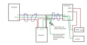
Is this grounding scheme correct.
-Purple circle means twisting these wires together.
-Chassi screw will be near to psu board(but not on it) so to avoid single wires running long.
Attachments
Last edited:
No.
Looks like you have the NTC going into the wrong wire.
The Protective Earth (PE) wire goes direct to Chassis - PERMANENTLY !
The Main Audio Ground (MAG) is connected to most of the exposed conductive parts. That needs a connection to the Chassis. Some amplifiers (monoblocks) will tolerate a direct connection from MAG to Chassis.
Many two, or more channel, amplifiers will have more noise if the MAG is directly connected to Chassis. In this case you may be able to attenuate that noise in a correctly wired amplifier by using a Disconnecting Network (DN) between the MAG and Chassis. That DN MUST be able to pass Fault Current. That Fault Current can approach and even exceed kA (1000Amperes). A resistor will almost certainly blow open circuit if you tried to pass Fault Current through it.
Read the ESP article, since you seem to have ignored all the warnings about putting resistors into the PE wire posted hundreds of times in this Forum.
Last edited:
No.
Looks like you have the NTC going into the wrong wire.
The Protective Earth (PE) wire goes direct to Chassis - PERMANENTLY !
The Main Audio Ground (MAG) is connected to most of the exposed conductive parts. That needs a connection to the Chassis. Some amplifiers (monoblocks) will tolerate a direct connection from MAG to Chassis.
Many two, or more channel, amplifiers will have more noise if the MAG is directly connected to Chassis. In this case you may be able to attenuate that noise in a correctly wired amplifier by using a Disconnecting Network (DN) between the MAG and Chassis. That DN MUST be able to pass Fault Current. That Fault Current can approach and even exceed kA (1000Amperes). A resistor will almost certainly blow open circuit if you tried to pass Fault Current through it.
Read the ESP article, since you seem to have ignored all the warnings about putting resistors into the PE wire posted hundreds of times in this Forum.
You referring to this article?
Earthing (Grounding) Your Hi-Fi - Tricks and Techniques
Read the ESP article, since you seem to have ignored all the warnings about putting resistors into the PE wire posted hundreds of times in this Forum.
I was referring to this particular comment.
Is this the article you asked me to read?
Earthing (Grounding) Your Hi-Fi - Tricks and Techniques
Yes i am placing thermistor in post#16
- Status
- This old topic is closed. If you want to reopen this topic, contact a moderator using the "Report Post" button.
- Home
- Amplifiers
- Pass Labs
- Please help with my F5 turbo wiring layout