Recommendations wanted for F5 PSU PCB that is currently for sale
Hi all,
First post here after lurking through many months of intensive scholarship. Now it's build time!
I'm putting together an F5 but having trouble choosing a PSU / rectifier combo. As neither PassDIY or DIYAudio are currently selling PSU boards, I've been hunting for something appropriate online. I'm wanting to keep this amp all PCB based...
The contenders seem to be... On the one hand:
Jim's Audio (eBay) - various designs. Seemingly anauthorised Pass "copies"
CRC Power Supply PCB Terminal Blocks Thermistor Are Included | eBay
And on the other hand - Something a lot more upmarket:
Sjöström Audio SPS01
Sjöström Audio - SPS01 Sjöström Power Supply
If I opt for the Sjostrom design, feeding it with the oft-used Antek 2 x 18V, is there anything I'd need to do to tweak the "out of the box" BOM? Or will this provide appropriate output to feed into my DIYAudio F5 boards without modification?
I already have 8 x Mundorf 22.000µF/40V M-Lytic AG caps and Mills resistors on the way, taking inspiration from this post:
http://www.diyaudio.com/forums/blogs/dvb-projekt/824-first-watt-f5-amp-build.html
Thanks guys!
Last edited:
Chipamp?
I have not built one, but I think I've seen people recommend this one Aleph Power Supply PCB | Chipamp Electronics. Try searching the F5 thread?
I have not built one, but I think I've seen people recommend this one Aleph Power Supply PCB | Chipamp Electronics. Try searching the F5 thread?
I have not built one, but I think I've seen people recommend this one Aleph Power Supply PCB | Chipamp Electronics. Try searching the F5 thread?
Yep seen that one thanks... Hoping to be able to make use all 8 caps I already have though
")
I have not built one, but I think I've seen people recommend this one Aleph Power Supply PCB | Chipamp Electronics. Try searching the F5 thread?
yes
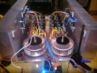
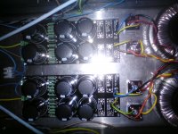
F5 dual mono with this boards. but with external dual bridges.Attachments
Nice looking ampyes
What transformers have you used for that, and also - any reason you didn't do the rectification on the PSU boards - simply to use the case as a heat sink?
Nice looking amp
What transformers have you used for that, and also - any reason you didn't do the rectification on the PSU boards - simply to use the case as a heat sink?
it is 2*18V 225VA RS transformers.
the reason for external bridges, was to get dual bridges. and to make sure they get the cooling they need.
http://www.firstwatt.com/pdf/prod_f5_man.pdf last page
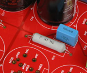
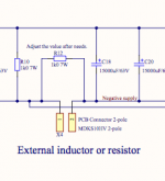
Nelson has chosen 0R47 3 W x 4 in parallel
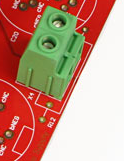
In my case you skip the green terminal and solder the resistor in place R11/R12
Bleeder 2k2 3W
In my pcb you can use 7 W resistors
Nelson has chosen 0R47 3 W x 4 in parallel
In my case you skip the green terminal and solder the resistor in place R11/R12
Bleeder 2k2 3W
In my pcb you can use 7 W resistors
Attachments
http://www.firstwatt.com/pdf/prod_f5_man.pdf last page
Nelson has chosen 0R47 3 W x 4 in parallel
In my case you skip the green terminal and solder the resistor in place R11/R12
Bleeder 2k2 3W
In my pcb you can use 7 W resistors
Hi PA... (if I may call you that
Just to clarify... To get the required 25V output, do you mean:
1. Omit the terminals X3 & X4
2. Add 0R47 3W x 4 in parallel (or equivalent) in R11/R12
3. Leave your R9/R10 as 1k 7W, or should this be 2k2 3W as per Pass PSU R9/R10?
I have already ordered 10 x 0R47 3W - Should I change to 7W, what is the benefit?
And any suggestions on how best to make this fit nicely on the PCB? Do I need to piggy back them on top of each other or am I misunderstanding what you are suggesting.
Thanks! lhalha
Attachments
You don't have to have bleeder resistors. They are there if you want the power supply to be discharged faster at switch off.
It's more practical to have only one resistor.... but you can build a stack with four resistors.
So are you saying:
Add one 0.12R 7W resistor in R11 and R12 (instead of stacking 4 x 0.47R)?
Use the bleeder value of 2.2k for R9 and R10 from the Pass circuit for slow and cool discharge?
Yes?
- Status
- This old topic is closed. If you want to reopen this topic, contact a moderator using the "Report Post" button.
- Home
- Amplifiers
- Pass Labs
- Available F5 PSU PCB options? Jim's -> Sjöström!?