Hi All
back again
well the saga continues.
Fets have been matched, to within 0.01v
All semi's on suspect channel have now been replaced..
except diodes..
the problem remains , one side is till running cold - the negative side.
No heat from mosfets, no voltage across the source resistors and -32v at the speaker terminal
still essentially back where i started after a lot of work - and some expense...
Any ideas..?
thanks in advance.
Hi All
Back again
new developments.
In short it appears on of the lower mosfets keeps on "shorting"
In my amp i have 3 upper and 3 lower output irfp240's
the one that keeps shorting is that which is fed by a 220ohm resistor -not only on the gate but also the source-fed from one of the mpsa42 transistors (or in some iterations this appears to be a ztx450 or mpsa18).
I have managed to replace the mosfet - powerup and get 20mv offset at the speaker terminals and a sensible Vgs measured across all the output mosfets.
after a few minutes the offset shoots back up to rail voltage and the VGs dissappears...on all the lower mosfets.
Upon removal of the suspect mosfet -testing of it shows VGS back to normal whilst it is out of circuit, ie : the mosfet itself tests ok as do those still in circuit.
Replacing the mosfet back into the position from where it came causes immediate failure....
what gives.?
Zenmod- i'm not sure what photos would show as it's unchanged for the last 4 or so years...
many thanks in advance
what can I tell you , except - observe for burned parts , cold solder joints , proper mosfet fastening on heatsinks ,shorts , traces continuity, blahblah
considering that's my day job - those things are simple for me ...... so I'm having just one approach developed - start from start , go methodically , and finish ..... on end
replace small bipolars ( cheap , no matching ) , start with just one pair of mosfets in output (one upper , one lower ) , then add second then third pair
funny - I'm sort of visual oriented kind of guy ........
so - we can chat till Judgment Day , and I can't give you more than generic advice , if you don't give more details
pull out all mosfets , check them all at current as in circuit , then mount back just one pair and test the amp ;
if one pair passes , add another pair .......... test ......... add another pair
if pcb isn't defective , I see no reason that amp not behave
do you have a CRO ?
use attached file for detailed info what range of measuring values to expect
Attachments
Thanks Zen mod
I'll give it another go
I did post earlier voltage settings based on the attached image , But i think they may have changed as i "seem" to zero in on the one dodgy mosfet position.
As i stated earlier the mosfets when removed from circuit and tested as though I was matching them again seemed to be working...VGS was consistent with earlier readings.
Again many thanks for the support.
Cheers
I'm also going to replace the small pcb that is home to the 3 lower mosfets to see if that has any effect.
Yes i do have a CRO, though only a single channel....
Ok A bit of an update
Mosfets installed one by one -and fired up and voltages measured and they are in accordance with those shown on the standrad aleph schematic- ie across a couple of resistors and the ztx450's, source resistors etc.
Until ... the last mosfet goes in - that is the one on the bottom side and as before has the 220ohm resistor going to the junction of the mosfet source and the source resistor.
at this point I fire up the power supply and monitor VGS of that particular mosfet and it starts off ok..
output is fine -no appreciable offset.
Than about a minute or so later the Vgs starts to plummet downwards until the speaker output suddenly jumps up to dc approaching rail voltage. (this is observed on the CRO as the Vgs drops)
I switch off asap.
With the 30mhz CRO I could see no oscillations at the output -... good I suppose..)
Anyway after power down the suspect mosfet is removed and examined- the back of the mosfet (metal side) now looks as though some surface plating has melted - must be getting rather hot!
Yes the mosfet is always bolted down to the heatsink.
measuring the mosfet VGS after reveals it to be as before....but in circuit the Vgs drops to almost 0 v.
I am almost at the point of scrapping this channel and doing a complete rebuild...
As you may have noticed, there are only a limited number of parts involved.
ZM is right, though, you are not giving enough information, particularly a
schematic with lots of voltage points on it.
If you have a Variac (tm) then you can run the circuit at low voltage and
it will still give good information.

ZM is right, though, you are not giving enough information, particularly a
schematic with lots of voltage points on it.
If you have a Variac (tm) then you can run the circuit at low voltage and
it will still give good information.
Many Thanks Gentlemen.
I have no variac sadly-mabe i can put a light bulb in series with the mains...
I did post some voltages at line 4 of teis discussion, but that was before this issue of the recalcitrant mosfet location..
I shall have another go of measuring point voltages but I now need to replace the pcb sub board that is home to the dodgy mosfet triple side, the pcb traces now having disintegrated from so many removals and insertion of mosfets....
BTW the gate resistor seems to be fine in location and connection.
A sincere thanks....
btw -this process makes a mess of one's wife's sewing bench.....
I've been reading a bit and am now starting to wonder if oscillation may be part of the problem depsite not being able to spot it with the cro......
I read that some physical elemnts around the mosfets could be causing grief - in particular the cheapo and nasty source resitors (wire wound ceramics) -( it can be hard to get decent quality parts around here at times...) - I'm thinking of replacing them with 10 off 10ohm metal film resistors in parallel and see what happens.
Alternatively and as I had to do some years ago - i placed some small caps pf ? across the gate /source (?) on an early mosfet amp which was prone to oscillation (eventually it shut iteslf down by actually catching fire..)
I wonder if the same may be useful here .
I am keen to investigate this as it may be a learning experience and may particularly be of benefit to someone else on the forum as sadly I am dissappointed that I seem to be able to contribute less myself compared to all the great assistance I've received over the years -it feels a bit unbalanced.
I will try to get the point voltages once the thing is stable - which i think it is with the problem mosfet removed...
Cheers
Using the diagram you posted at the start...
If you remove Q104 and 105 and Q107 and 108 does the amp work normally ?
Only the current through Q106 is used for monitoring the current so the amp should work and be stable. If you can confirm it is then add the next pair, Q104 and Q107 and test again or as you say only the lower right ? fet causes problems, just remove that and its complement and test.
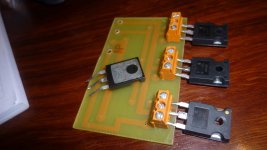
Ok Daughter board about to be rebuilt. (I have some spares)
having got rather tired of unsoldering / resoldering the mosfets i've elected to mount them using screw terminals .
This also allows to easy exchange in place for matching Vgs in situ.....
see attached photo
resting on top of the daughter board is one of the mosfets that got rather hot - you can see the melting of the plating on the rear.
Interestingly Vgs still measures ok on this one!
Attachments
- Status
- This old topic is closed. If you want to reopen this topic, contact a moderator using the "Report Post" button.
- Home
- Amplifiers
- Pass Labs
- Aleph 5 DIY- with Dolphin sounds...Help please