Hi All
Back again
after various pressures and priorities I found myself doing a complete (newish) build as I had a couple of spare A5 pcbs floating around....
It worked first time with all voltages ok...so that is very reassuring and pleasing .
So the A5 is installed back in the system and singing as sweetly as ever.
though not very hot as its fan cooled with large heatsinks (only abt 15deC rise over ambient..)
I really don't know what the problem was but interestingly a few odd parts appear to have fried themselves without me noticing - particularly the Source (1 ohm ) resistors.....
Anyway - I now have a few mosfets to check for damage (some shorted and some reading a very low Vgs..)
I still don't know what the problem was - and will as time allows do a rebuild on my 2 spare pcb's with the intention of placing them in my triamp system to cover 80hz-650hz, the repaired Aleph is covering from 650hz up...
One issue that has arisen is that when I fired up the amp I connected a "sacrificial" speaker just in case something was untoward- no probs except for buzz which is not really noticable on the main speaker (ribbon).
Now that I have an oscilloscope i had a look at the output with inputs shorted and noticed an odd looking waveform. ($40 for a 2nd hand CRO- money well spent!)
The strange waveform was also present on the power supply + & - with no load attached (no amplifier load as it a 2 box unit and I disconnected the power feed to the pcbs')
It could be some dodgy caps (4 x80kuF) or the diode bridges (2 squre box style wired in paralle.
I'll post an image of the waveform to see if anybody cleverer than I knows what it means ..
Most importantly - a big thanks to all have helped in getting the amp working again.
Your guidance , suggestions and observations are all very much appreciated.
I hope i can return the favor to the forum every now and then.
cheers from down under
")
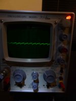
well here tis
photo of scope view- as best as i can do
frequency of pulse i think equates to 100hz with abt 0.03v peak to peak voltage. (yes i calibrated the scope)
this is taken at the terminal of one of the power supply caps with no load on the power supply other than some bleeder resistors- abt 160ohms.
amp is totally disconnected.
power supply consists of:
a) 1 trafo - supposedly 50v ct with 50A secondary
b) 2 diode bridge blocks in parallel
c) 4 of 80kuF caps (total for + &-ve)
d) 160ohm bleeders per rail.
e) 1 small cap across one of the diode bridges
when i connect the amp i can hear a bit of a buzz through a highish efficieny speaker, but is pretty inaudible with the ribbons the amp usually drives.
amp is connected to the ribbon via a matching transformer.
Is the waveform telling us anything?
thanks in advance
Attachments
Sawtooth ripple like is what you would expect to see. That all looks perfectly normal.
If you can hear this ripple (and it will be far higher than 0.03 v pk/pk with the amp drawing current) then the two main possibilities are a less than perfect wiring scheme whereby some of that voltage is developed across and conductor and finds its way into the amp, and/or the ripple rejection of the amp itself allows some ripple present on the rails to pass to the output.
If you can hear this ripple (and it will be far higher than 0.03 v pk/pk with the amp drawing current) then the two main possibilities are a less than perfect wiring scheme whereby some of that voltage is developed across and conductor and finds its way into the amp, and/or the ripple rejection of the amp itself allows some ripple present on the rails to pass to the output.
thanks Mooly
I'll try the 1k bleeders first - after that it may be worth adding an inductor to the PS to make CLC e.g.. 80kuF 2mH 80kuF...each side
i have a few 2mH inductors lying around somewhere - about 1mm2 wire though- ex speaker crossover - air core..hmm would they do?
less than perfect wiring scheme-er, um, maybe hmmm, definitely maybe...
Thanks

 )
)thanks Mooly
I'll try the 1k bleeders first - after that it may be worth adding an inductor to the PS to make CLC e.g.. 80kuF 2mH 80kuF...each side
i have a few 2mH inductors lying around somewhere - about 1mm2 wire though- ex speaker crossover - air core..hmm would they do?
less than perfect wiring scheme-er, um, maybe hmmm, definitely maybe...
Thanks
Not so sure they would do much tbh.
This is a wandery thread but have a look at posts #14 and then skim through looking at the diagrams I drew. It might give you some insight into where things go wrong with wiring.
http://www.diyaudio.com/forums/solid-state/101321-3-stage-lin-topology-nfb-tappings.html#post1623053
well here tis
photo of scope view- as best as i can do
frequency of pulse i think equates to 100hz with abt 0.03v peak to peak voltage. (yes i calibrated the scope)
this is taken at the terminal of one of the power supply caps with no load on the power supply other than some bleeder resistors- abt 160ohms.
amp is totally disconnected.
power supply consists of:
a) 1 trafo - supposedly 50v ct with 50A secondary
b) 2 diode bridge blocks in parallel
c) 4 of 80kuF caps (total for + &-ve)
d) 160ohm bleeders per rail.
e) 1 small cap across one of the diode bridges
when i connect the amp i can hear a bit of a buzz through a highish efficieny speaker, but is pretty inaudible with the ribbons the amp usually drives.
amp is connected to the ribbon via a matching transformer.
Is the waveform telling us anything?
thanks in advance
I question both the use of "b) 2 diode bridge blocks in parallel" and "e) 1 small cap across one of the diode bridges." George A, can you clarify the thinking behind these?
- Status
- This old topic is closed. If you want to reopen this topic, contact a moderator using the "Report Post" button.
- Home
- Amplifiers
- Pass Labs
- Aleph 5 DIY- with Dolphin sounds...Help please