Your ground loop is a combination of the internal star and the external IC's.
First, figure out if it is trapping outside the chassis or in. Take a very short rca cable and connect input to input. If you still have the hum, it is internally generated. If the hum goes away, it is external. You may be able to short ground to ground internally with a simple wire, and if that loop closure causes the hum, enough said.
External, you may be able to eliminate it by wrapping the two IC's together to close the shield loop as much as possible.
btw, if your heatsinks are getting hot, you're oscillating. Be very careful with your tweeters/crossovers. Some of the recommendations given so far may be causing oscillation.
The pics are extremely useful for troubleshooting, btw.
jn
Last edited:
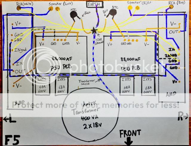
This is Star Grounding.P.S Remove your black and blue wire between amp boards.

Basi,
The troublesome aspect of this is the drawing puts the speaker ground current in close proximity to the input ground. Coupling between them can cause oscillation.
jn
I am happy to announce that I am no longer having and hum/buzz problems and I believe I have fixed my ground loop.. I just reconnected my preamp and (for some reason unknown to me) my speakers are silent..
Now I am terribly worried about this possibility that my F5 might be oscillating... The drawing isn't exactly how I ended up wiring it. I was given like 3 different pieces of advice and I really just picked the one that sounded best. Here is what I did..
Speaker ground =>Amp PCB
Rca Ground => Amp PCB
Amp PCB => Main Audio Ground
PSU =>Main Audio Ground
Main Audio Ground =>CL-60=>Safety/Chassis Earth
So my main audio ground has 4 connections (2 PSU PCB, 2 Amp PCB)
It seems that the RCA ground and speaker ground might be in contact with each other through the Amp board or Main Audio Ground...
The pics are in post #40
Ah, ok.
First, never use green wires for output hot and output ground...you are confusing the electrons...
")
Seriously..
Twist the output wires together tightly so that they do not create large magnetic fields in their vicinity. Run the twist up to a point halfway between the two spots on the board where they connect.
For all designs, try to keep the opposing currents closely together. For the supply rails, if there is a plus and minus feed to a board, twist the two together with the ground feed. That way, all positive current is close to the return path, negative current is also, and even cross conduction (a bad thing) will not produce large fields.
edit: On the transformer primary side, I note a loop between the terminal block and the back panel thing. That loop will create fields that will communicate with the star ground wires, so that loop must be eliminated by twisting the wires together.
On a personal preference note: do not use green for AC hot or AC neutral conductors, use it only for safety bonded ground. Use white for neutral. (note, this is in the USA).
jn
Last edited:
My ground loop has totally vanished, which I am quite happy about. My system is hum free. Thanks so much everyone for your help. I have learned a lot.
Now I am now worried about oscillation. I didn't know twisting output wires together would be the right thing to do. I have read to only twist the inputs.. V- and V+ are tied together with zip ties, but not twisted..
Are these concerns related to oscillation? I am worried about my speakers now. Not that they are humming but that they might EXPLODE or something..
Any thoughts on oscillation after looking at my configuration would be great. Then I will leave you guys alone.
I am about to complete my DCB1. I am just waiting on a chassis from Italy...
Now I am now worried about oscillation. I didn't know twisting output wires together would be the right thing to do. I have read to only twist the inputs.. V- and V+ are tied together with zip ties, but not twisted..
Are these concerns related to oscillation? I am worried about my speakers now. Not that they are humming but that they might EXPLODE or something..
Yes, they also relate to oscillation. It is always best to twist together conductors which carry current to and from two objects, so that the fields are constrained as much as possible. Supply rails and transformer primaries are not immune to this.
I added to my previous post, you may wish to re-read it.
I'd worry only if your heatsinks were still getting hot. If it's oscillating, either look with a scope or substitute an 1/8th watt 8 ohm resistor at the far end of the speaker cables as a sacrificial lamb so to speak. If your speakers are in harms way, that resistor will toast.
jn
Ok, I will go back in a twist the wires together that you recommended.
I will also borrow a friends scope and check the waveforms on output.
Of course, the heatsinks get hot just like every other F5. I just have no way of knowing what temp is too hot. Maybe I am overreacting. I mean, they arent too hot to touch or anything. I mean, I can put my face or hands on the sinks indefinately without too much discomfort whatsoever. I will look for a temperature gauge to check this out more precisely.
Are there any tests I can perform to troubleshoot the possibility of oscillation? Shorting inputs, etc..?
Basi,
The troublesome aspect of this is the drawing puts the speaker ground current in close proximity to the input ground. Coupling between them can cause oscillation.
jn
No if they are connected like a drawn in post 24.
Greetings!!!
Ok, I will go back in a twist the wires together that you recommended.
I will also borrow a friends scope and check the waveforms on output.
Of course, the heatsinks get hot just like every other F5. I just have no way of knowing what temp is too hot.
Are there any tests I can perform to troubleshoot the possibility of oscillation? Shorting inputs, etc..?
Scope is best.
From your earlier post, I thought your sinks were getting hotter after a mod. That is why I was thinking osc.
24 is indeed a bit better. Note however, that the output wires are not twisted around the ground. That loop can induce into the input ground loop.No if they are connected like a drawn in post 24.
Greetings!!!
Remember, even though the input pair is twisted, they will still form a ground loop with the other pair at the preamp. That entire loop will be sensitive to broadcasted magnetic fields.
jn
Yes i agree Output wires must be twisted and away from input like power wires.Scope is best.
24 is indeed a bit better. Note however, that the output wires are not twisted around the ground. That loop can induce into the input ground loop.
Remember, even though the input pair is twisted, they will still form a ground loop with the other pair at the preamp. That entire loop will be sensitive to broadcasted magnetic fields.
jn
I was only draw basic star ground sheme to help madisonroberts to resolve ground loops.There is many more tricks in audio design but that is not the question in this thread.I'm very pleased that madisonroberts resolve the problem and learn in the way.
Sorry for bad English.
Greeatings!!!
What I really need to do is get a thermometer and get an exact temperature reading. They sinks do feel hotter (i think) and they seem to be getting hotter faster. Although, It could be that I was not paying as much attention before this mod.
I will go in and twist the output wires as well as the AC wires to the barrier strip.
Hum is gone, I am a very happy camper.
Thanks everyone for your help!! I will keep this thread updated with anything related to my former problem.
Regards
I will go in and twist the output wires as well as the AC wires to the barrier strip.
Hum is gone, I am a very happy camper.
Thanks everyone for your help!! I will keep this thread updated with anything related to my former problem.
Regards
Yes i agree Output wires must be twisted and away from input like power wires.
I was only draw basic star ground sheme to help madisonroberts to resolve ground loops.There is many more tricks in audio design but that is not the question in this thread.I'm very pleased that madisonroberts resolve the problem and learn in the way.
Sorry for bad English.
Greeatings!!!
Your english was clearly up to the task, as it certainly helped madisonroberts..
Good job.
jn
post40
The last pic shows all those Hot wires without the corresponding Return wire, for maximisation of Loop Area.Ok here are some photos of my new isolated Main Audio (Star) Ground. It is isolated from chassis using nylon screw and nuts. All connections are in contact with each other, but are not in contact with the chassis. Main audio ground is connected to Chassis/Safety Earth via CL-60 thermistor.
The last two photos are of my grounded grid preamplifier. There is a ground bus wire connecting all the RCA jack grounds. This ground bus is connected to Chassis/Safety Earth via a small 1/4 watt resistor.
Last edited:
- Status
- This old topic is closed. If you want to reopen this topic, contact a moderator using the "Report Post" button.
- Home
- Amplifiers
- Pass Labs
- F5 Ground Loop - Need Ideas..