Thanks Zen, will do. I thought that R5 is one of the resistors to change. Just a solder slingers guess.
This morning I installed another op-amp in my op-amp phono pre with 2 db more gain and the BA-3 has enough oomf with enough volume right now but it would be nice if I can use it with my J-fet phono pre as well. I think I will go with 68 ohms to start. Right now with a higher gain phono pre the sound has more authority with my F4. The F4 is one of, if not, my favorite amplifier among the 6 finished FW clones I have.
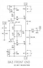
About to forget, same schematic used.
This morning I installed another op-amp in my op-amp phono pre with 2 db more gain and the BA-3 has enough oomf with enough volume right now but it would be nice if I can use it with my J-fet phono pre as well. I think I will go with 68 ohms to start. Right now with a higher gain phono pre the sound has more authority with my F4. The F4 is one of, if not, my favorite amplifier among the 6 finished FW clones I have.
About to forget, same schematic used.
I have built this preamp several years ago. Some uf of PP´s in the output and was not so impressed.
Now I revived it. First finding: the nominations of P1 and P2 in the schematic are reversed. Had quite some fun.
With Silmics in the output the preamp is overly polite. With Nichicon FG, KZ and biplolars it is much more fun but still a bit recessed.
I changed the gain according to Zenmod and Andrew - and everything is fine now. Very open and dynamic.
Many thanks.
I really should be working right now, but I could not resist ")
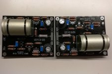
Version b of my boards arrived after almost 2 months in customs. The crisis is now messing with our hobbies as well...
Anway...
They seem to bias up nicely, and the FQP pairs seem very close without any matching.
Here is some porn

Version b of my boards arrived after almost 2 months in customs. The crisis is now messing with our hobbies as well...
Anway...
They seem to bias up nicely, and the FQP pairs seem very close without any matching.
Here is some porn
Attachments

Anyone know how I can simulate the load the ba-3 preamp circuit has on the power supply? Can a resistor be used?
I have an AN-0512 Antek 12v-0 12v-0 secondary wired in series for 24v. Im getting odd reading with no load on the regulated power supply. The reg power supply manual says to use a load to get proper readings.
It's an LM317/LM337 based regulator.
I want to test the power supply before connecting it to the ba-3 preamp circuit. What value resistor, if any, can be used?
Thanks
Vince
Are you feeding the PSU 0-24v and trying to make it into a bipolar +24 -0- -24 ?
That doesn’t work...
Using both secondaries in series.
The reg accepts ac 0 ac.
Thanks ZM.
Vince
Yes, they are in series, and with the center of the two secondaries as the virtual center tap you’ve still only got 24v across the entirety of the windings... in a perfect world you’ll only get +15 -0- -15 after rectification, diode drop and regulator dropout.
If your transformer was a AN-0518 or -0520 you’d be able to get +/- 25v
If your transformer was a AN-0518 or -0520 you’d be able to get +/- 25v
You are right 6. I was going by this graphic.
https://www.electronics-tutorials.ws/transformer/multiple-winding-transformers.html
I have a 22v as-0522 to drop in.
Thx
Vince
https://www.electronics-tutorials.ws/transformer/multiple-winding-transformers.html
I have a 22v as-0522 to drop in.
Thx
Vince
Ok, perfect! your -0522 will work beautifully. You'll have about 30v at the regulator inputs, and that's close to ideal for making the regs happy.
The graphic you linked is correct - it's just that a bipolar +/- 24v supply is actually two 24v supplies in series, and we choose to call the connection point of those supplies "GND", But there's still 50v from one side to the other.
The graphic you linked is correct - it's just that a bipolar +/- 24v supply is actually two 24v supplies in series, and we choose to call the connection point of those supplies "GND", But there's still 50v from one side to the other.
Last edited:
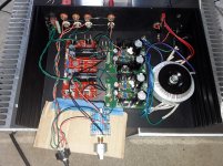
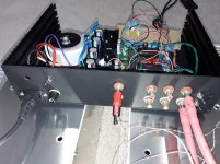
One more..
High\low gain switches
Dayton Audio precision 10uF caps
317/337 regs
24v operation
Galaxy case
Pure silver rcas
Fairchild mosfets
LS jfets
Antek as-0522 transformer
Budget stepped pot
Silver contact selector switch
Generic copper wire
Face plate needs milling.
Driving MoFo monoblocks
Vince
High\low gain switches
Dayton Audio precision 10uF caps
317/337 regs
24v operation
Galaxy case
Pure silver rcas
Fairchild mosfets
LS jfets
Antek as-0522 transformer
Budget stepped pot
Silver contact selector switch
Generic copper wire
Face plate needs milling.
Driving MoFo monoblocks
Vince
Attachments
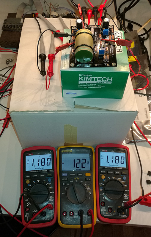
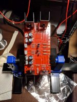
I began building this weekend. The PCB from the DIY store is a very good. It looks like its gold (ENIG).
Attached is a picture of the board in progress. Everything is populated except the output cap which allows easier access to take measurements.
Inputs are K170/J74 and the outputs are K2013/J313.
The power supplies are + / - 24V. The unclipped output is 40 v p-p. The gain is just a little over 10X. This seems a lot lower than what NP states in his article. I assume this is due to the gain of the output transistors. To increase gain, is it as simple as increase R6 and R7 or decrease R5?
The -3dB point is about 1 MHz. What a wide bandwidth. I assume I can shave that down with a larger input resistor?
- Home
- Amplifiers
- Pass Labs
- BA-3 As Preamp