Thanks mate
How come? Does it make the change faster?
Dont forget to short the inputs. Big difference in DC offset.
nash
Here we go. Some progress.
The pre seems to bias nicely even with random unmatched 610/9610. I am using them for tests so that I do not blow my matched Toshibas.
BTW I really hate how twitchy the pots are (Currently using 1k).
I finally go tired of this and came up with the following:
Having experimented with different bias levels and the resulting sound I found that a bias level of around 50ma sounded best to me. Besides 60ma was producing too much heat. I measured the pots P1 and P2(+ to end of R6 not joined to R8 for P1, and - to R7 for P2). I re-measured the pots after removing P1 and P2 from the boards. In my case with R6 being 56R I measured around 348R for P2 and around 6R higher for P1, this with very well matched Toshiba's.
I then installed a CMF 55 348R resistor in place of P2 on the board. For P1 I replaced it with a 20R pot in series with a 348R resistor since I wanted a measure of adjustability. Since this has to be in parallel with C1 (otherwise the AC gain of the amp is affected) I bent the pin of the pot closest to R6 so that it wrapped upwards along the pot, soldered the 348R resistor to it, wrapped it around the pot and now made that end of the resistor effectively the third pin of the pot. I also put a bit of insulating material at the bottom of the pot to prevent any contact between the resistor and the pot pin that was bent.
DC offset setting is so easy now. And you get similar results the next day after you have switched it off which never happened before. And there is plenty of adjustability. One turn of a 20R multiturn pot is around 0.65R and I find that you get around a 60mv offset change from just 1 turn. A 500R pot is around 16.5R per turn. No wonder it is so twitchy. I just did this mod a week ago. Maybe it even sounds slightly more detailed. The only change in DC offset I am now expecting is with a change in room ambient temperature.
nash
Which points are you using to read DC offset..a pic would be helpful.
Cheers
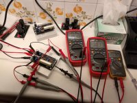
Here is a photo if it helps. You should be able to extrapolate where to attach the probes on your pcb.
The probes closer to the cap measure offset (back side of cap and output return)
Thank you so much for reverting, meanwhile I used the 330R resistor (R13 as per schematic), put probes around it an set DC offset...Have biased the amp to about 80%, will use it for some time then attempt a full bias...
Thank you so much for reverting, meanwhile I used the 330R resistor (R13 as per schematic), put probes around it an set DC offset...Have biased the amp to about 80%, will use it for some time then attempt a full bias...
Yes sounds correct. R13 is connected to the back of cap and output return
It's not clipping your F4 in it's stock configuration??? It should.
Not enough gain when using my phono, plenty with everything else. If it were a BA-2 build with the BA-3 board inside one would use a pre with gain for enough power but using a F4 which is just a power buffer the BA-3 pre does not have enough oomf without using another pre in front of it for my phono. My cartridge has an output of around 5mv and I have tried multiple phono pres using the BA-3 pre with the same result. In the BA-3 article Nelson says R8 and R9 help set the voltage gain but I would not think one would want to lower their values much below 100 ohms fearing oscillation. The gain of my LSK pre is more than the BA-3 and it does have enough gain with my phono but barely but it is pretty easy to increase the gain which Nelson does touch on in his video. Not a big deal I was just wondering if the BA-3 gain could be increased a few more db's.
in fact , what you need is BA3 FE with few more db of gain , to use as standalone preamp ?
Correct. Almost enough but it is apparent that the phono preamp output is less than 1V. With a 1V computer output there is plenty enough gain. In other words not enough input voltage using a phono pre even with horns. A couple more dbs should do it with my speakers. The BA-3 as a pre is already built along with the F4. I have thought about installing a BA-3 board inside the F4 much as the BA-2 with a BA-3 board but with a few more db's I believe the BA-3 pre would be more versatile.
Last edited:
AndrewT, yesterday I had the same thought. I have a couple of phono pres I have built, one a J-fet one and the other a op-amp. There is some difference between the two but nothing dramatic so I am just going to increase the gain on the op-amp one which is pretty easy. I am thinking 2 db gain will be plenty on the phono pre. I have a number of preamplifiers I have built and yesterday I increased the gain on a op-amp preamplifier to 15db gain and it has plenty of power to drive the F4 but sounds somewhat thin compared to the BA-3 pre. The BA-3 pre and the F4 is a great combination together but most already know this considering this is what is used building a BA-2.
will chime in tonight , with changes necessary for BA3FE
you can find guides both in article and in related threads , boyz were already crying for changes")
Thanks for the effort Zen. The BA-3 was not designed for a standalone preamplifier by Nelson but it has been considered very good by many of which I agree. But I like my LSK better. Quicker and more dynamic sounding to me. Our store needs a board for a preamplifier to compliment the many amplifier boards being offered. The LSK pre is an all J-fet preamplifier. I am shocked that there has not been more interest in this design. As Nelson said at BAF it has room for improvement of which our members are able to do. Way beyond my abilities but I like mine just as presented over any I have built.
as I wrote several times - I have an impression that BA3 FE , when used as line level stage - low gain and low output swing , is somewhat constipated
dunno - maybe other Greedy Boyz are having different opinion....
plenty of factors with which I can explain that , but let's leave my usual wild speculations aside
(ppl most probably aren't always in mood for my philosophy/SciFi concoctions )
dunno - maybe other Greedy Boyz are having different opinion....
plenty of factors with which I can explain that , but let's leave my usual wild speculations aside
(ppl most probably aren't always in mood for my philosophy/SciFi concoctions )
- Home
- Amplifiers
- Pass Labs
- BA-3 As Preamp