Building the Pass/Firstwatt F4
This is a fantastically good sounding amp - read more about it here before staring;
https://www.firstwatt.com/wp-content/uploads/2023/08/prod_f4_man.pdf
The thread at DIY audio -
http://www.diyaudio.com/forums/pass-labs/97540-f4-power-amplifier.html
And this the the corrected schematic (The schematic in the Firstwatt article has a typo, also this one agrees with the PCB)
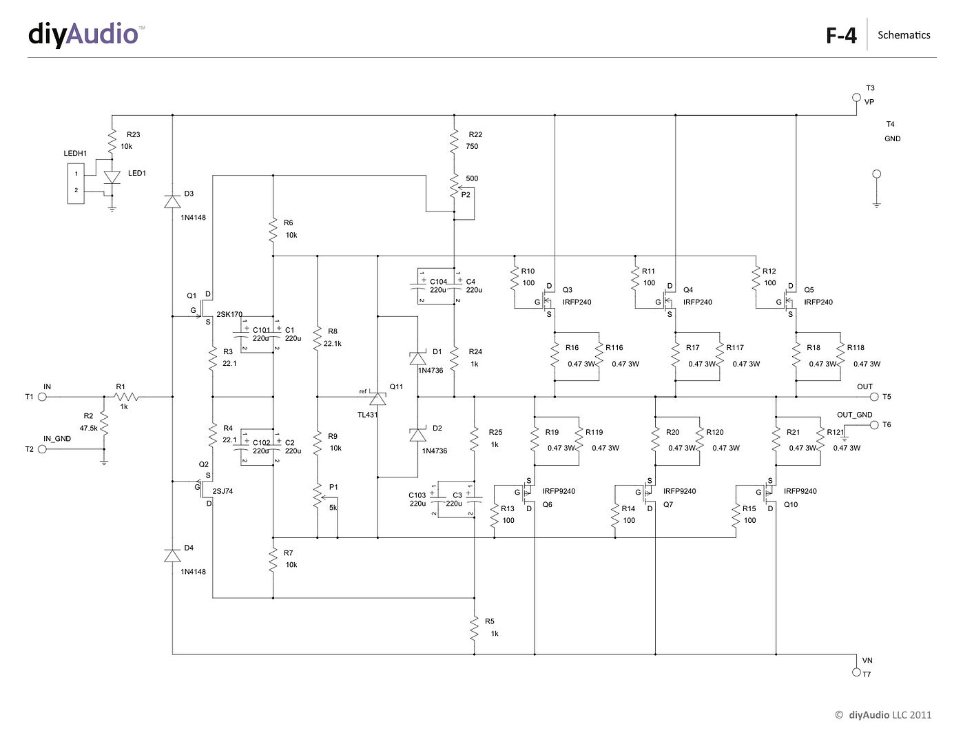
Here you will find a build guide for the Pass / Firstwatt F4 power amplifier using PCBs and chassis from the DIYaudio store.
The 5U 'BIG Amp Chassis' is shown, because that's the one I have. It will fit comfortably in a 4U 'Jack of all chassis' and have enough heatsink as well.
~~~~~
There are plenty of places that you could start, but for the sake of illustration let's begin with the heatsink assemblies -
This is the heatsink(s) from the 5U 'BIG Amp Chassis' It has a mirror-imaged set of pre-drilled heatsinks and brackets to hole them together and make a mounting point for the rest of the enclosure. The 4U is similar, but the heatsink is a single piece.
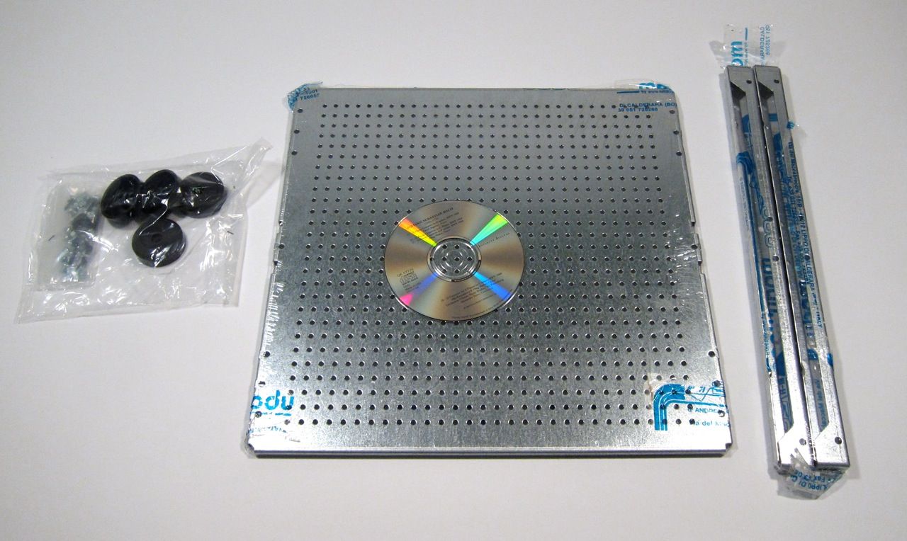
This build will also utilize the 'DIY friendly' baseplate, here shown with the feet and hardware, and also the heatsink's brackets.
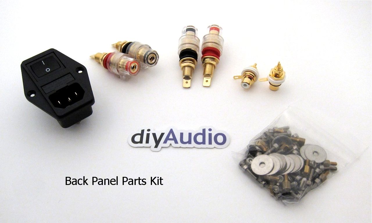
There is a hardware package available for the pre-drilled back and heatsinks, including input and output jacks, IEC module, and hardware for the PCB and heatsinks.
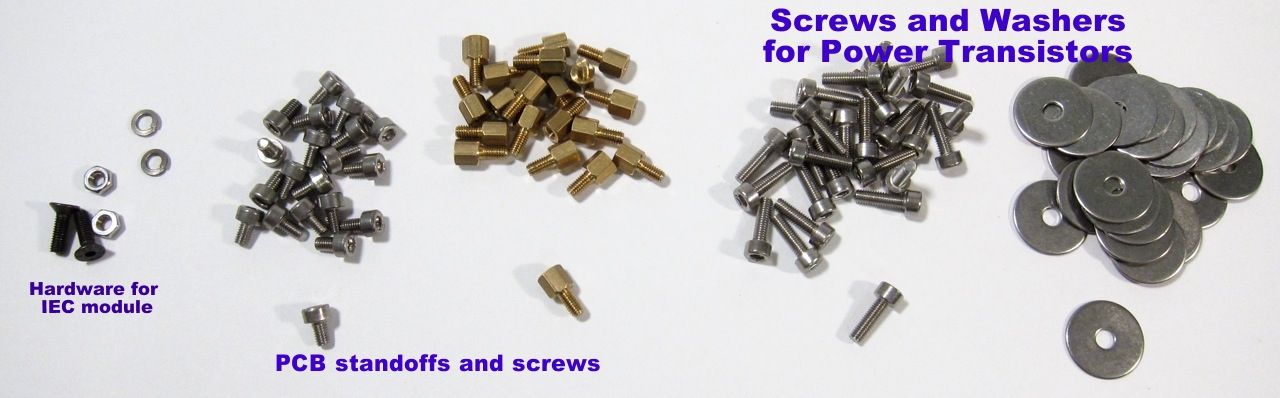
The contents of the hardware bag.
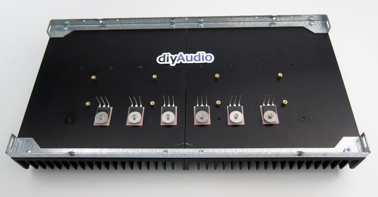
Using the brass PCB standoffs, install them into the PCB mount holes as shown, to get the following pattern;
Now there is a place to mount the amplifier PCB
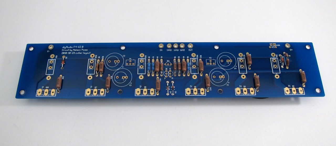
Speaking of PCB, it's a very nice layout, plenty of room, and the ability to use many sizes of resistors and caps. This is the front.
Here is the back.
Stuffing the PCB should be done in the usual order, from smallest device to biggest - so that would be diodes and resistors first.
Of note, I got the bigger (Dale/Vishay RN60) resistors to see how they would fit on the PCB. They are the size of the PRP resistors that are quite popular amongst the fancy parts crowd. They are great everywhere except the row flanking the small transistors right in the middle. They don't fit there side by side. You could mount them soldier style, or just mix in a few smaller resistors like I did. Or just get RN55's. They are the smaller size.
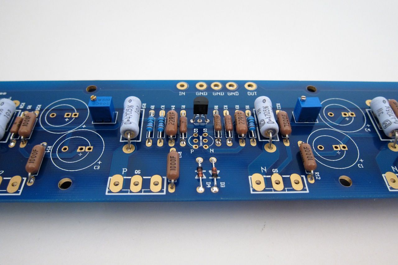
Pots and transistors next. (yes, I didn't stuff the input pair when the photo was taken…)
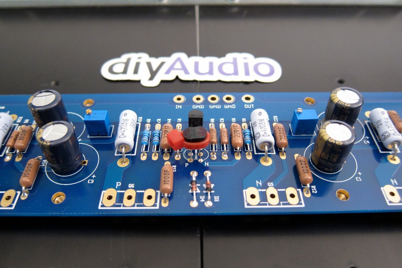
Ah, there they are.
The ziptie is just to help their thermal tracking.
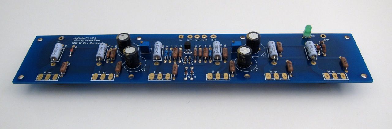
And finally the capacitors.
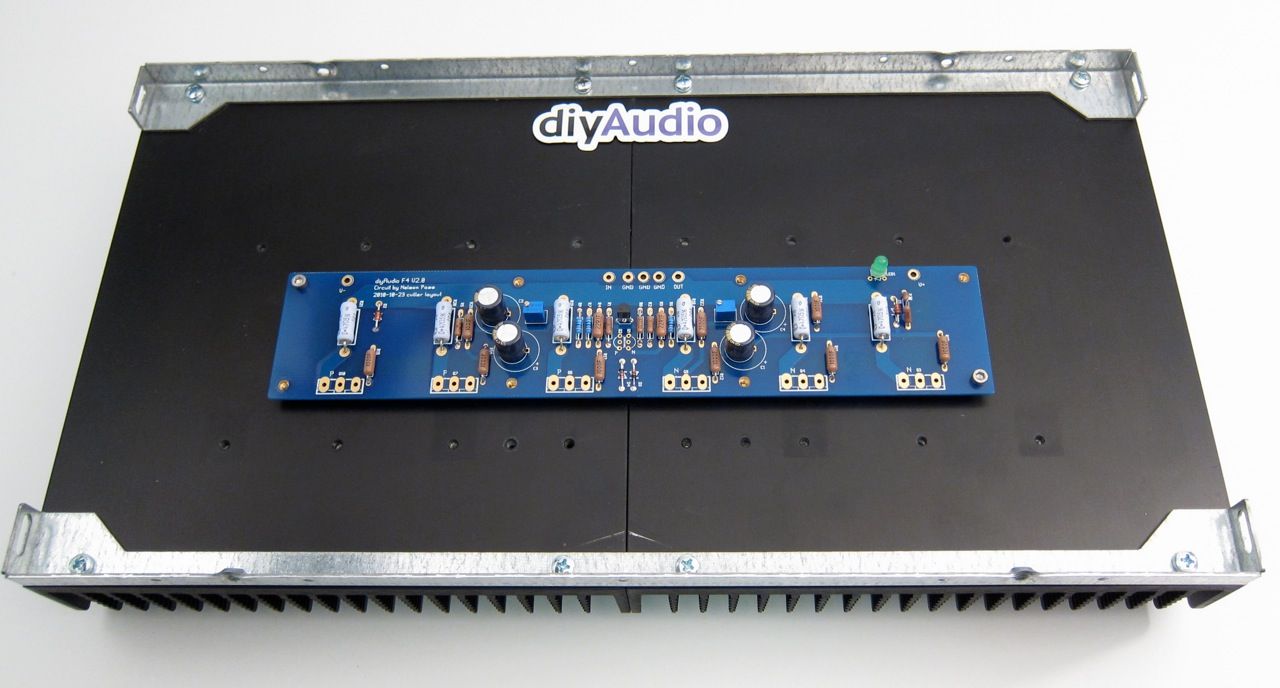
There is a top and bottom to the Universal Mounting Spec holes, the board mounts as shown
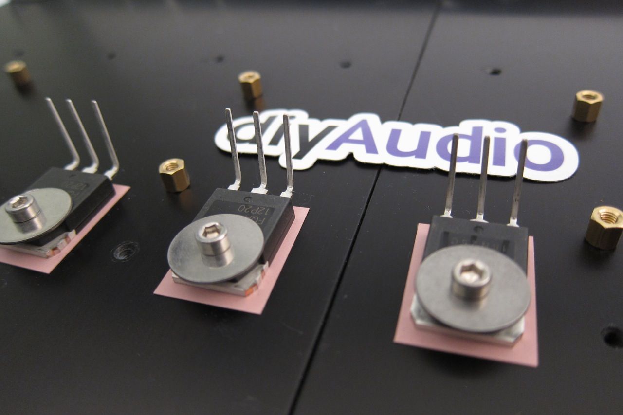
I find it helpful to bend the leads of the transistors first, and mount them (a little bit loose) to the heatsink.
Like this

And then mount the PCB. You can snug all the screws down and then solder and trim.
Ok, now lets move on to the Power Supply.
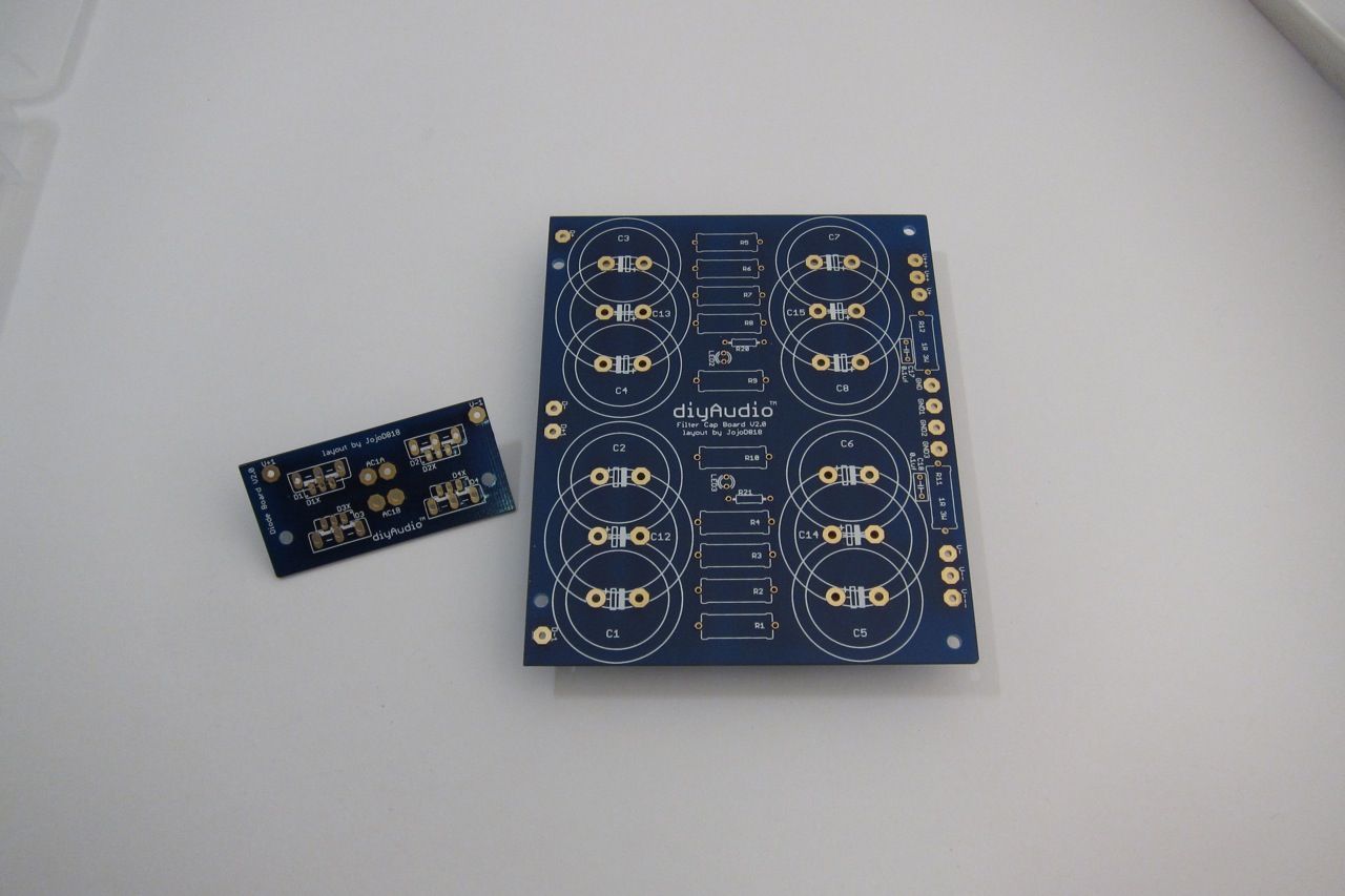
Here is a photo of the PSU board, I am going to use integrated bridge rectifier blocks, so you need to remove the part of the PCB that mounts the diodes. The new PCB, not quite yet available at the time of this writing, will have a similar feature with the diodes, as well as room for more/bigger capacitors.

As always, stuff the small components first - the light blue resistors are the filter resistors, the darker ones with the teflon are the bleeder resistors, and the small ones are for the LEDs.
This PSU board is the exact same DIYaudio PSU board, just without the top blue soldermask.
This shows the INPUT edge (from the diode bridges)
The capacitors are Panasonic T-UP 33,000uf 35V
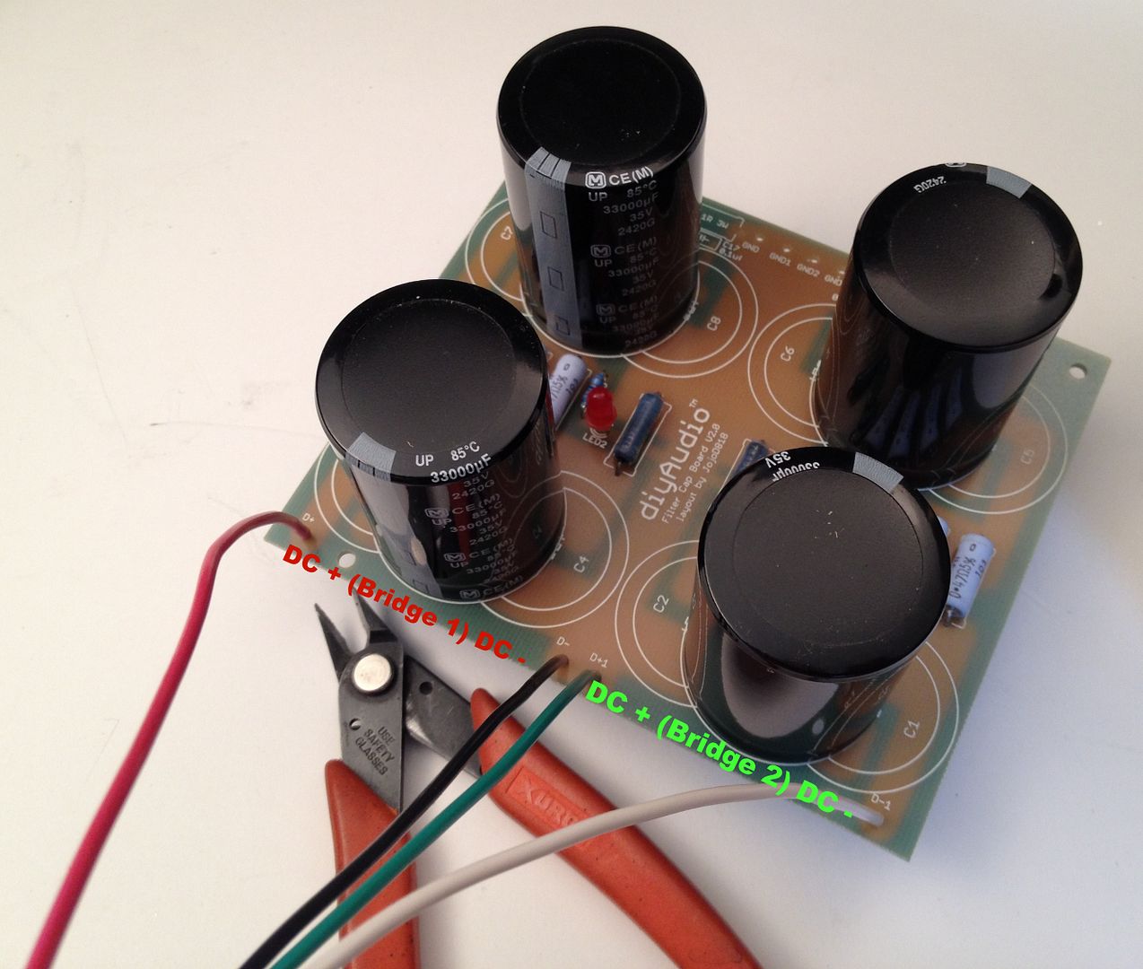
Connecting the bridges to the PCB
This is the OUTPUT edge of the PSU - the colors are
Red V+
White GND
Green V-
The black connects the PSU GND to the CL-60 to the chassis.
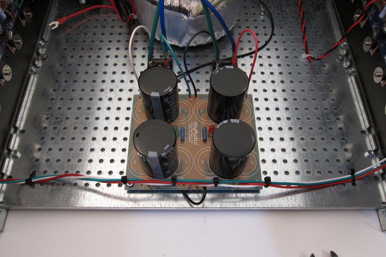
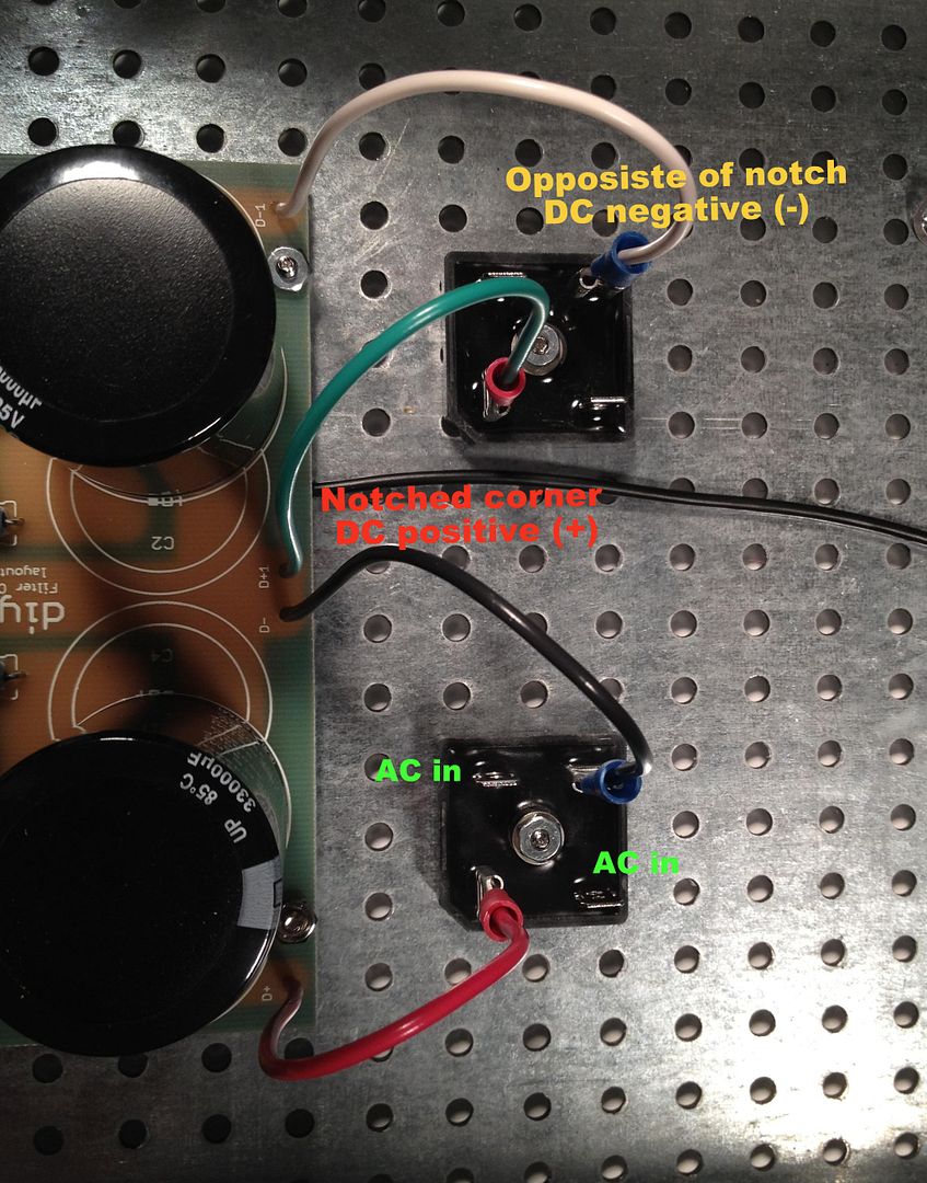
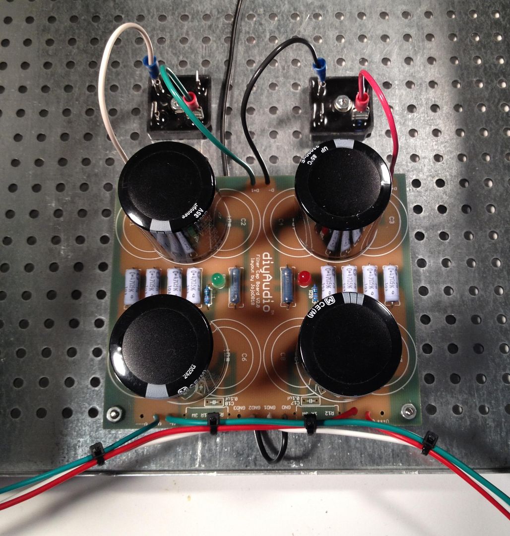
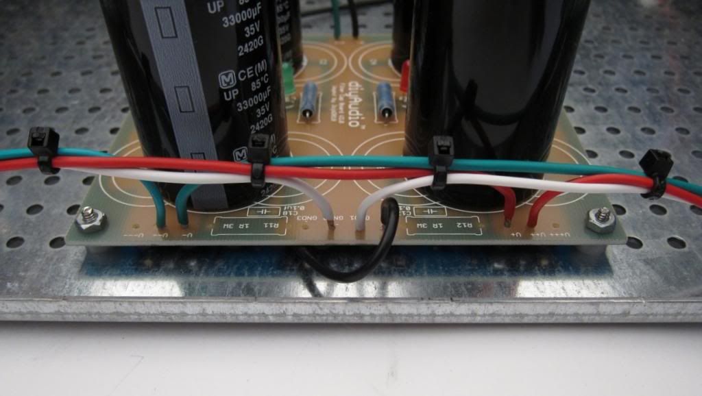
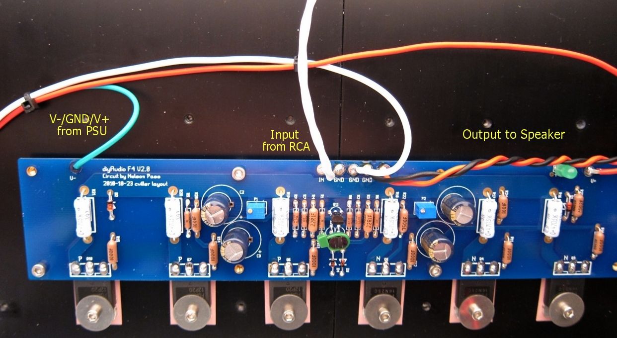
The wiring from the PSU to the amp PCB is clearly shown.
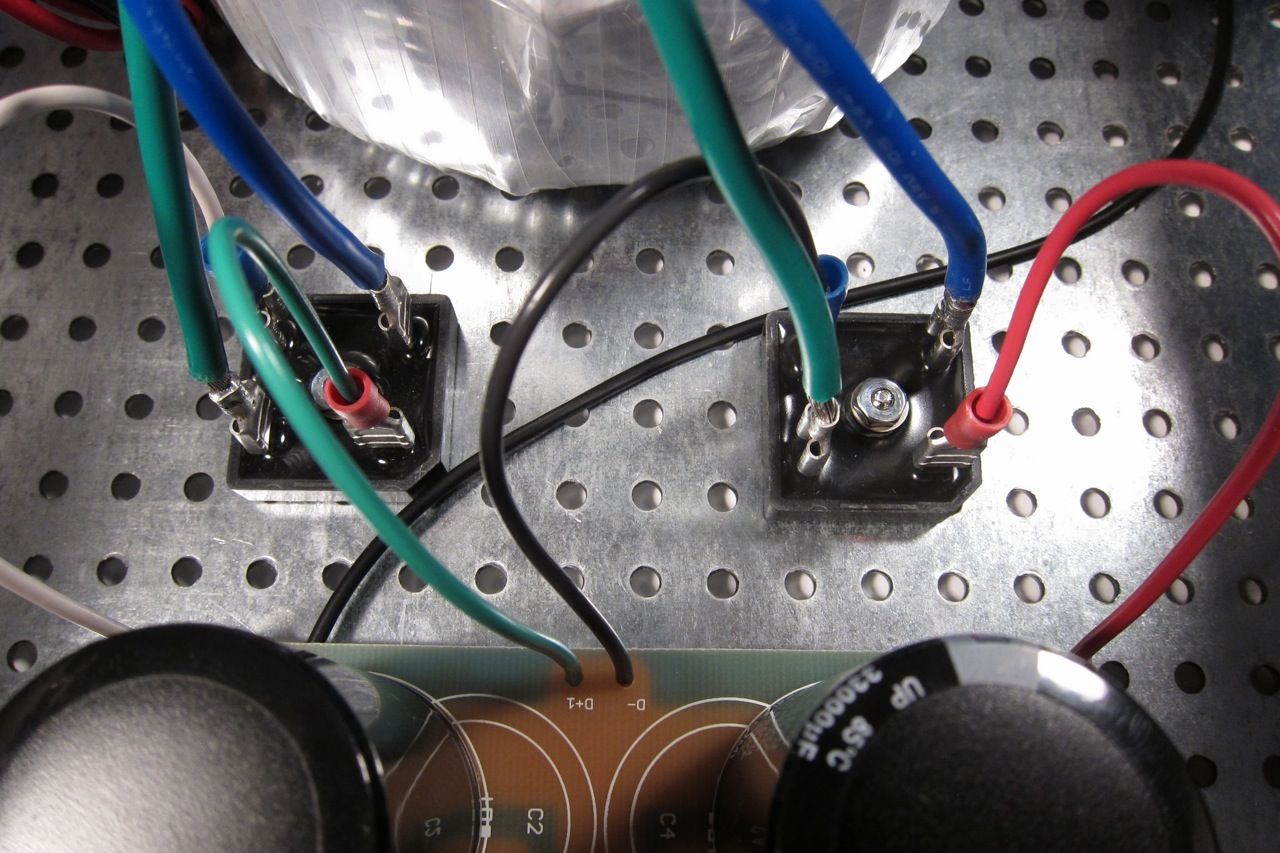
Here you can see the bridges with the wires attached from the transformer secondary. Remember that the green attached to a bridge must have continuity with the blue attached to the same bridge. (As it's the 2 ends of the same piece of wire)

As long as were are tailing about the transformer, here is a photo of the terminal block shown wired for 120v. The Blur lead is the AC Live, and the clear the AC neutral. The reds and blacks are the transformer primaries.
Transformer is an Antek 400VA 18v+18v, part number AN-4218.
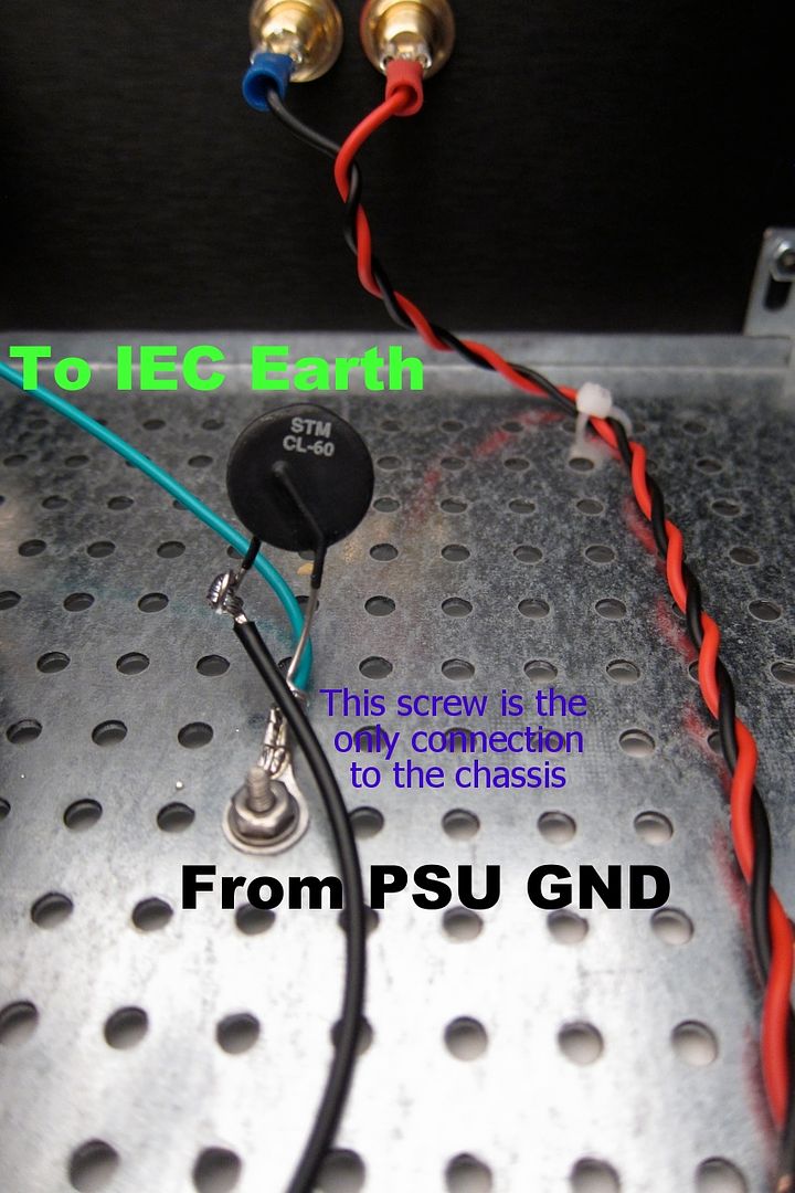
The last bit of the PSU wiring is the chassis connection, the black comes from the PSU GND, and the green is the AC safety earth.
The AC to primary wiring confuses everybody, so;
Let's look at the PSU schematic just to make sure everything is OK... Remember that I am wiring it for 120v operation, so the transformer primaries are in parallel. People wiring for 240 with a transformer like this, please ignore.
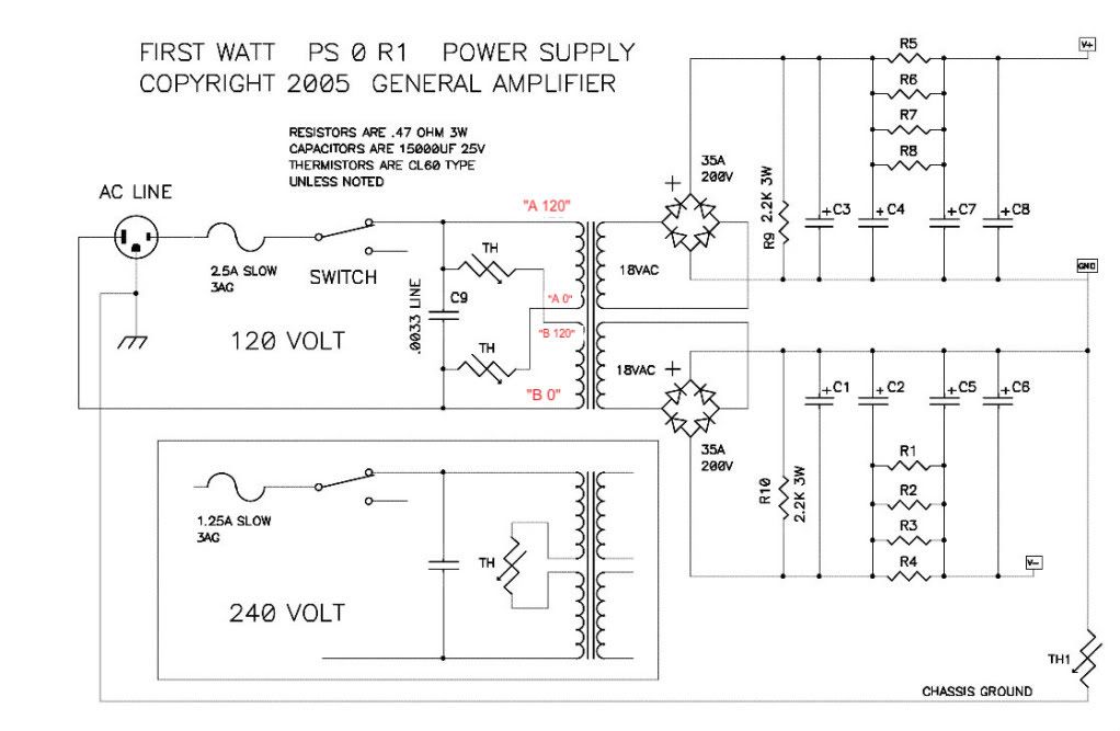
Notes in red are mine.
Look at the connections of the transformer primary, through the thermistors and line cap, to the mains.
Hot AC is connected to the "120" (which in my case is the red leads on the primaries) One red primary is connected to AC hot through a thermistor.
Neutral AC is connected to the black "0" leads, one of which is connected to the AC through a thermistor.
AC Hot and Neutral have a cap across the leads.
So, yes, the AC will be connected to the center 2 posts, which is across the cap.
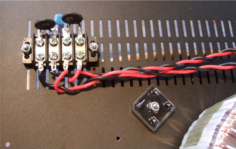
(This photo lifted from my F5 thread, but it's the same PSU…)
Left to right we have post 1, 2, 3, 4
POST 1 - Transformer primary 'B 0' which will be connected to AC Neutral at post 2, through the thermistor between post 1 and 2.
POST 2 - AC Neutral in (not shown in photo), connected to Transformer primary 'A 0" , a thermistor to post 1, and a line cap to post 3
POST 3 - AC Hot in, connected to transformer primary "B 120", thermistor to post 4, and line cap to post 2
POST 4 - Transformer primary "A 120", connected to AC Hot through the thermistor to post 3
If you look at the red and black wires in the photo you will see that the Mains AC must to pass through a thermistor to connect to each of the 2 primaries. And that is the point of them, to keep inrush under control during powerup.
Ok!
Now we need to put everything together -
But first a bit more mechanical assembly.
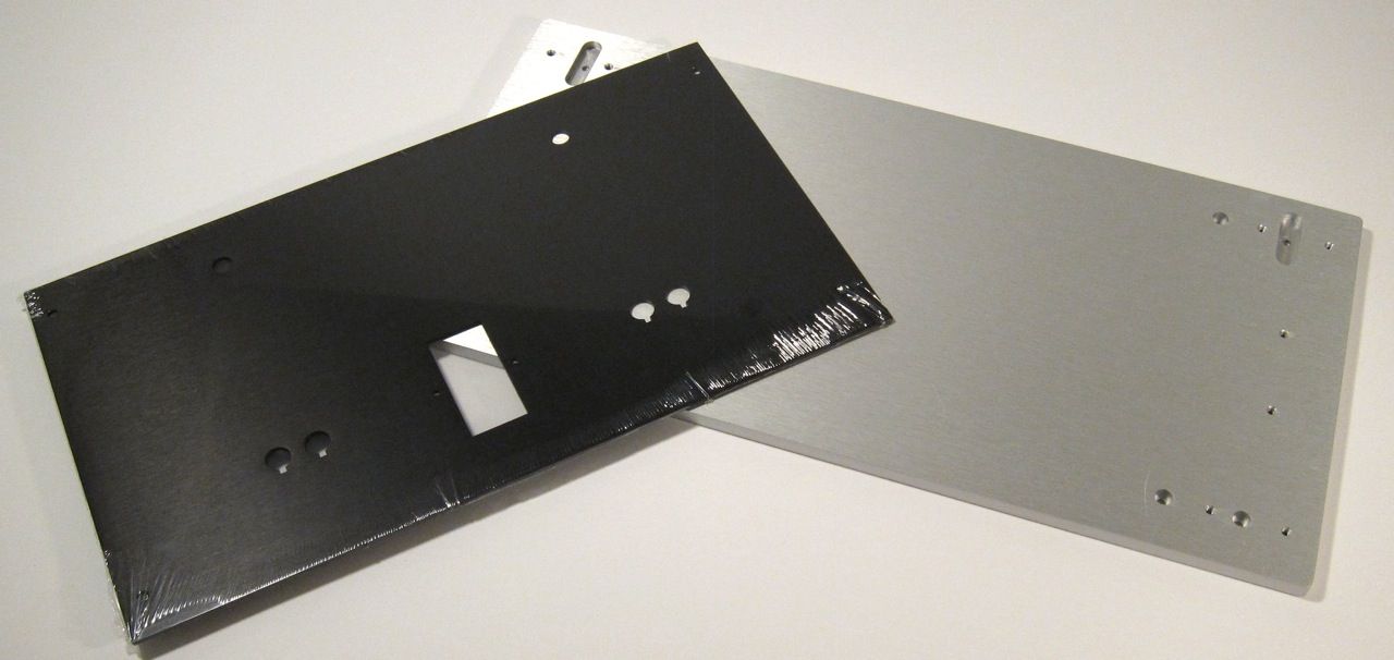
This is the pre-cut back plate and the thick front plate.
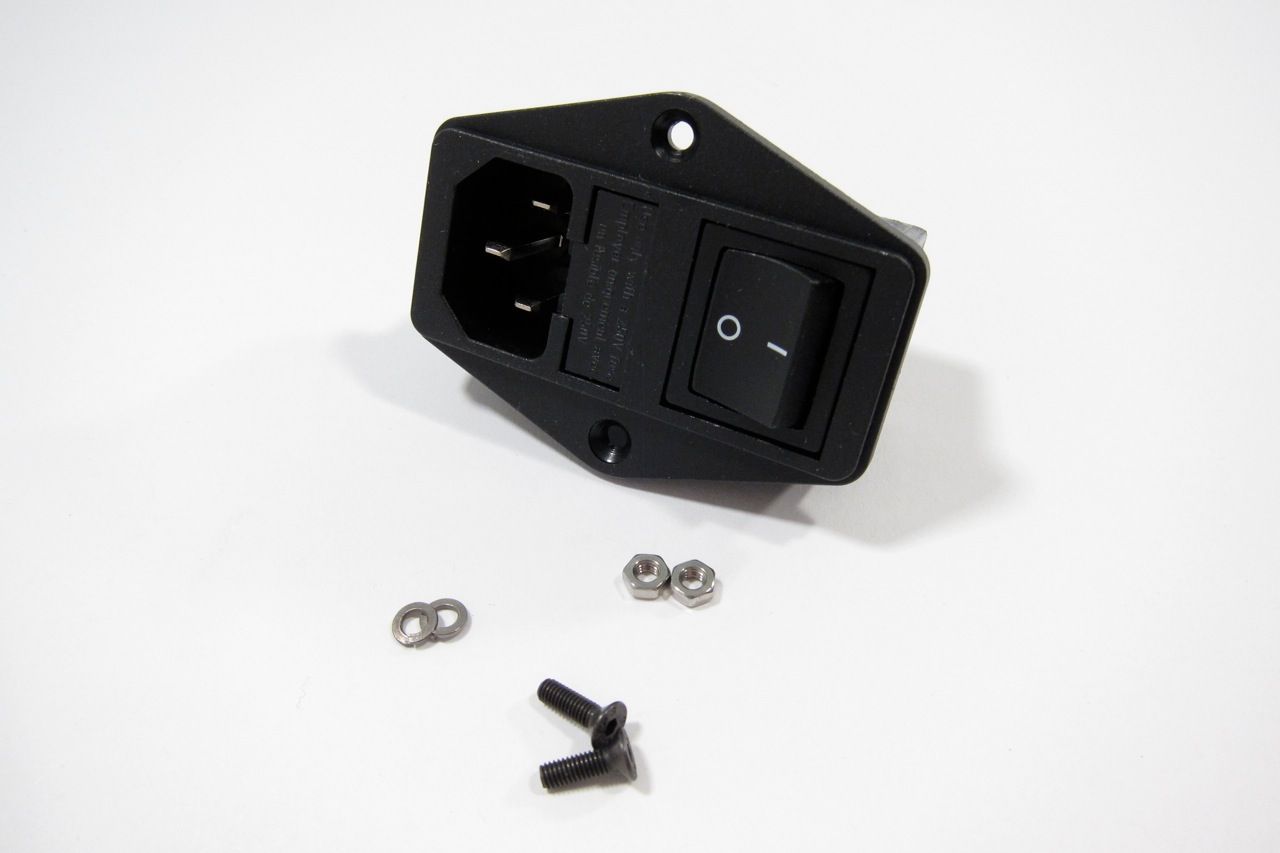
Gather and mount the IEC plug.
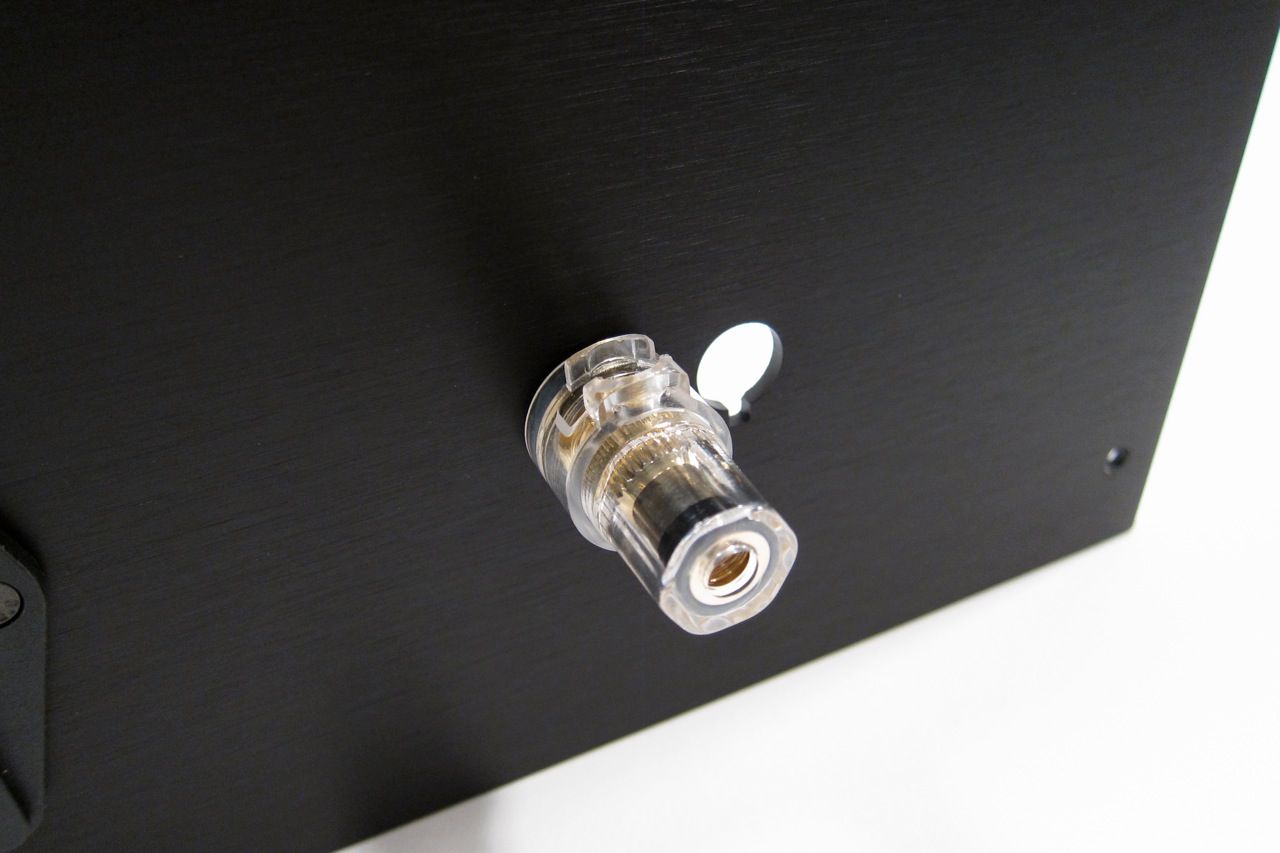
The speaker posts.
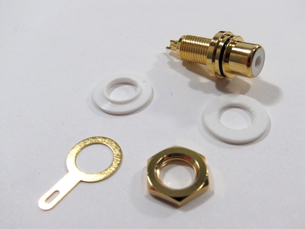
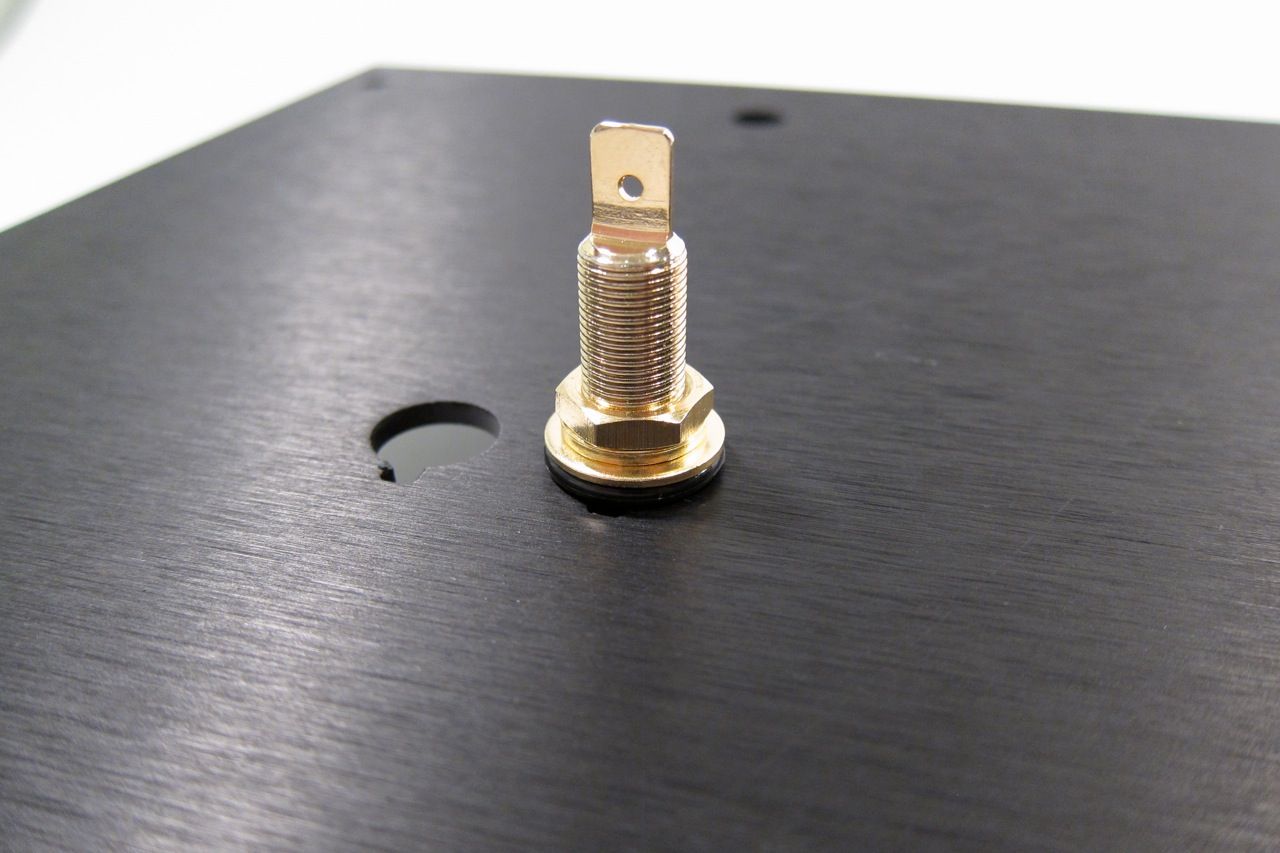
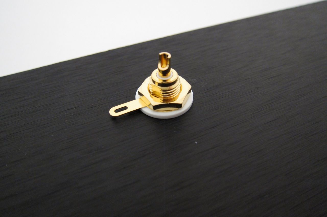
And the RCA jacks.
Note that the shoulder washer goes on the inside, so the metal of the chassis doesn't touch the metal of the jack. There is a similar washer on the speaker posts.
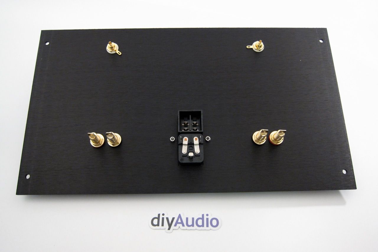
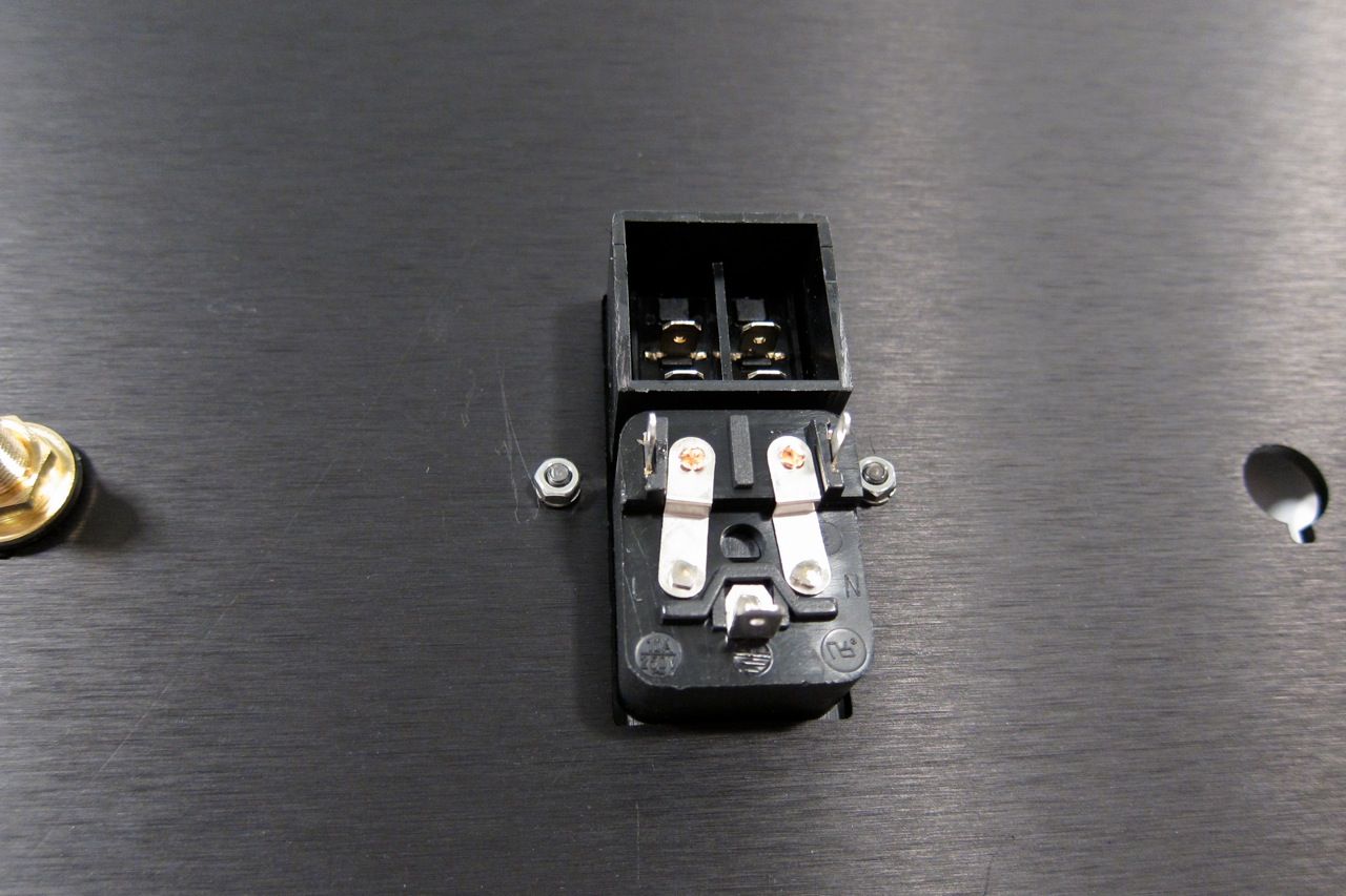
The inside of the back panel.
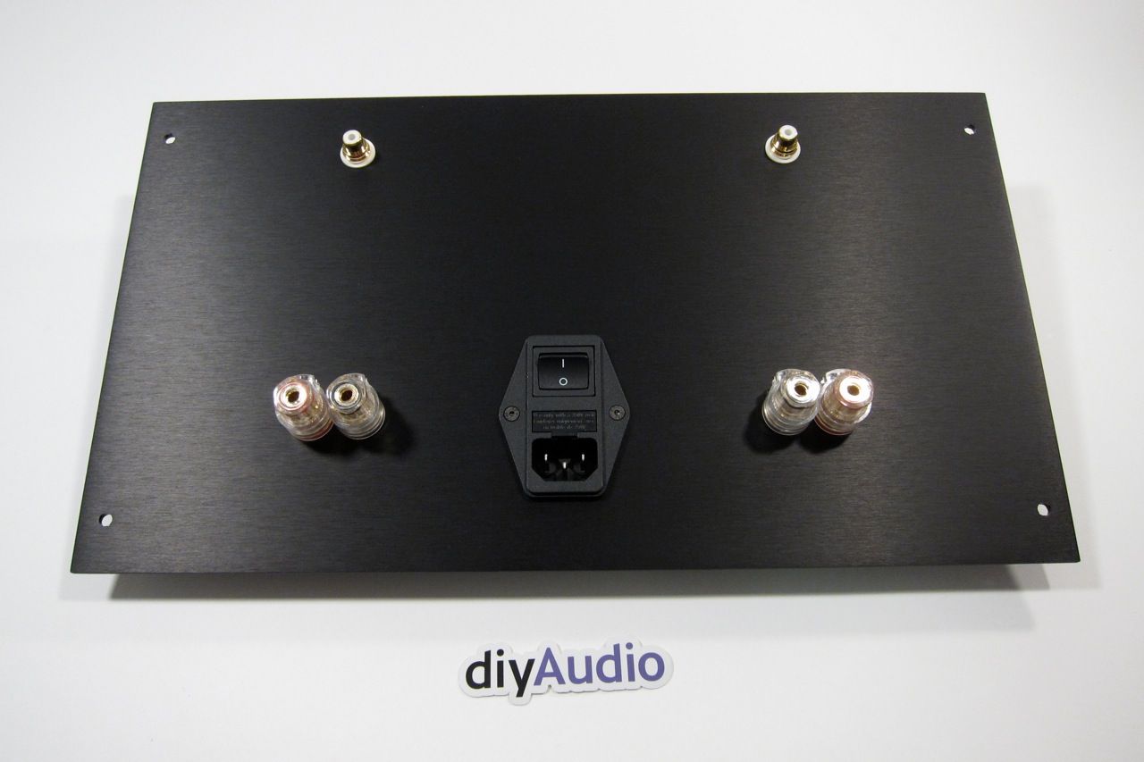
And the outside. Looks good, yes?
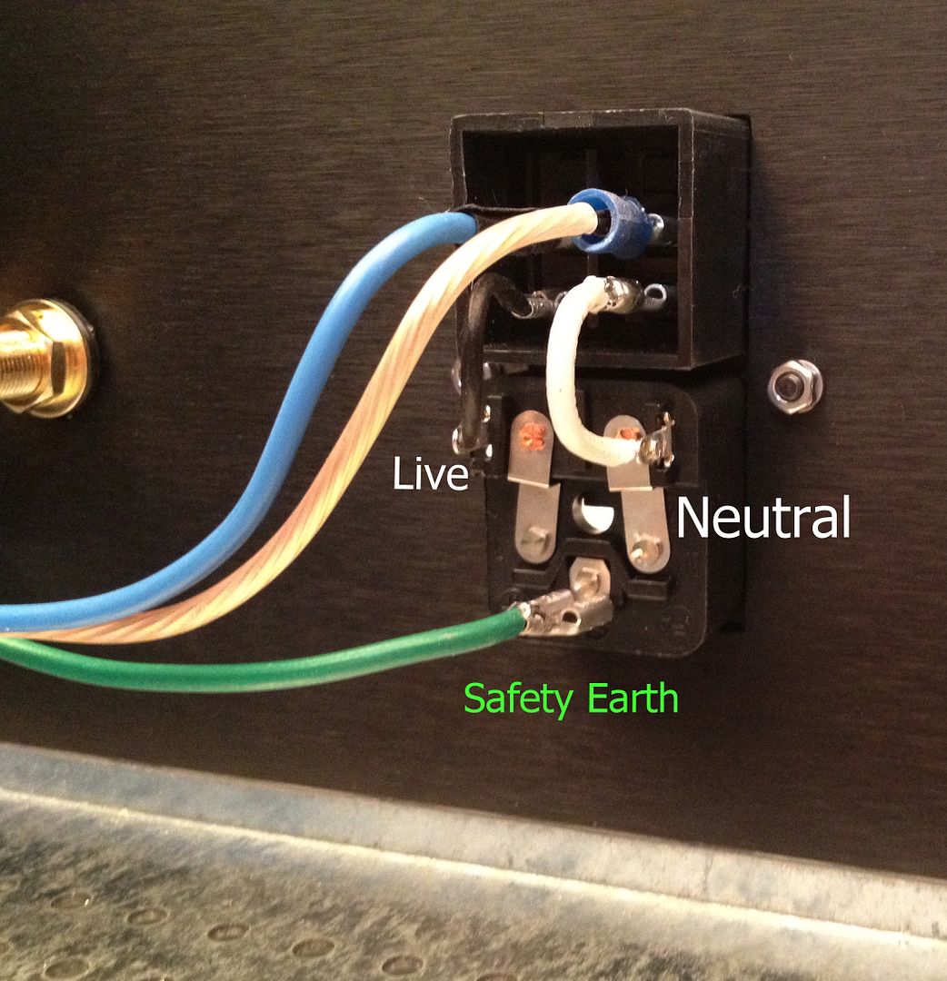
The IEC module is wired as shown. This will switch both the Live and Neutral. The blue (live) and clear (neutral) go the the wiring block with the thermistors, cap and transformer primaries.
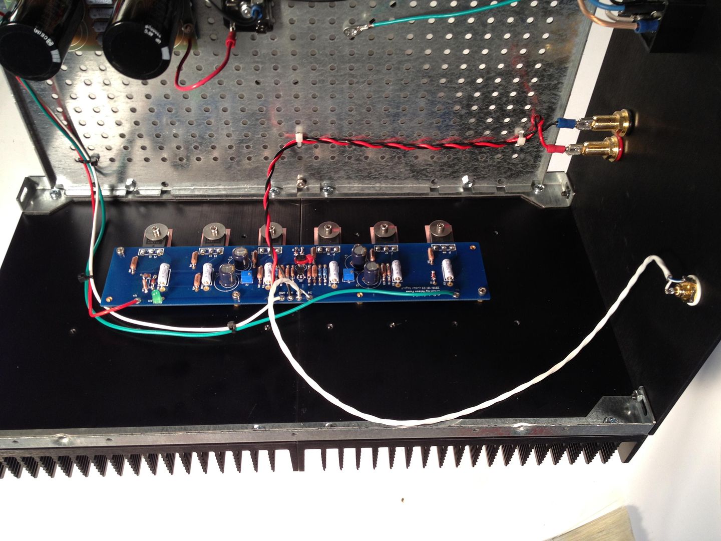
The amp PCB completely wired.
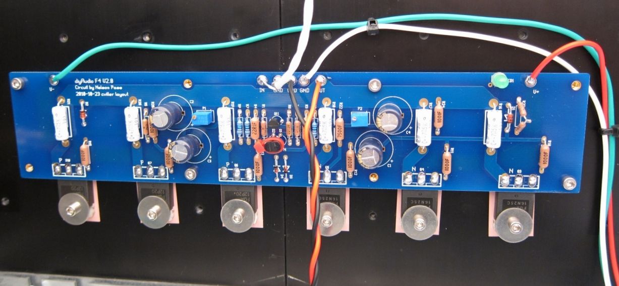
A bit closer.
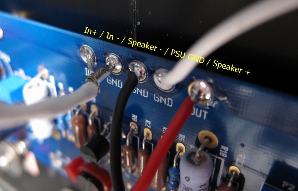
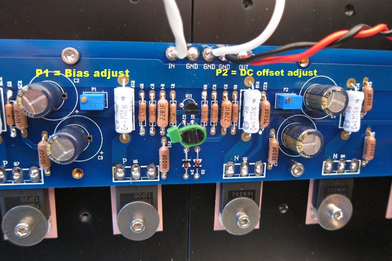
The top connections labeled.
This happens to be the other channel, but the connections are all the same.
Remember that V- / GND / V+ is always left to right as you are looking at the format of the PCB
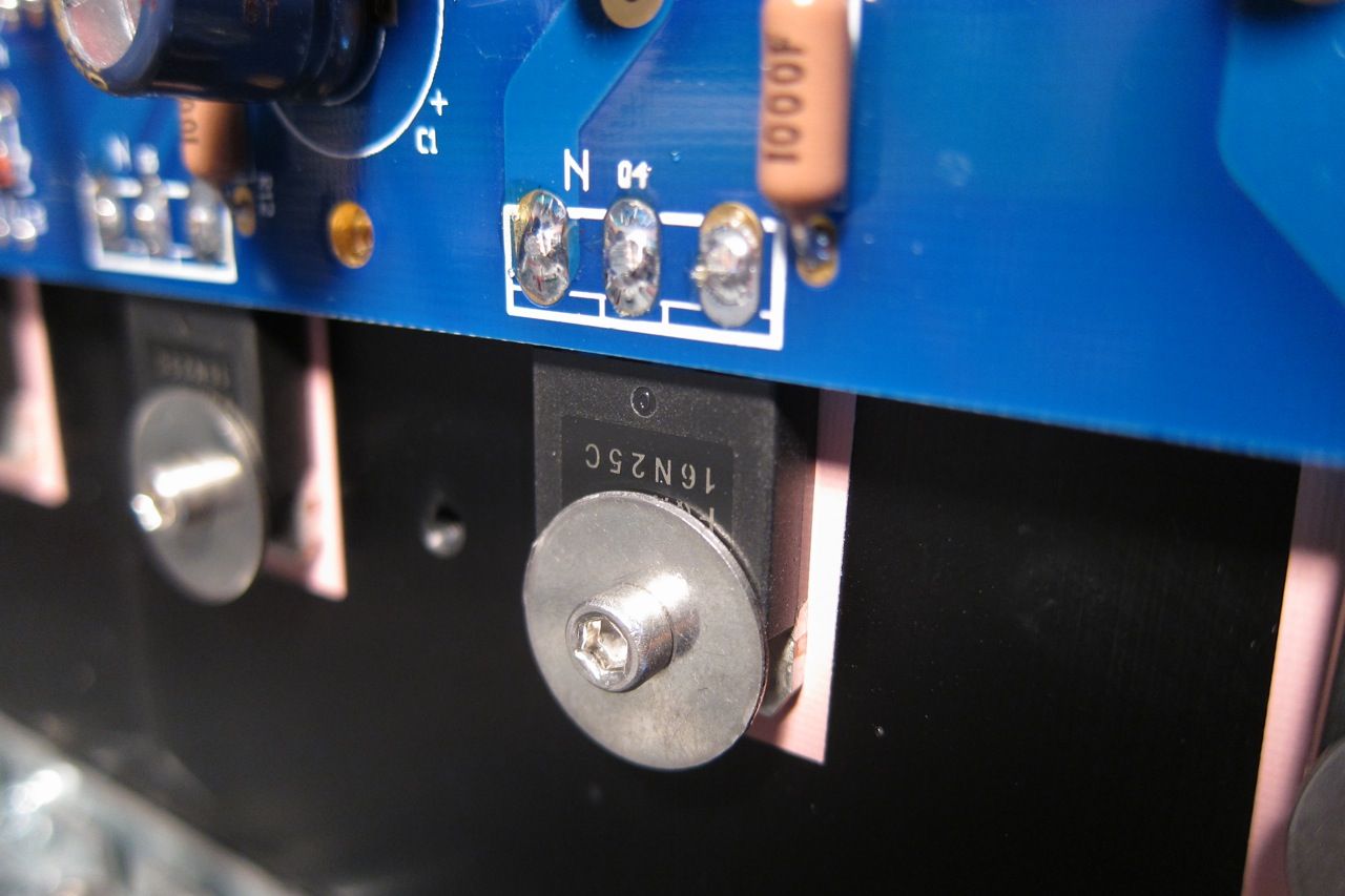
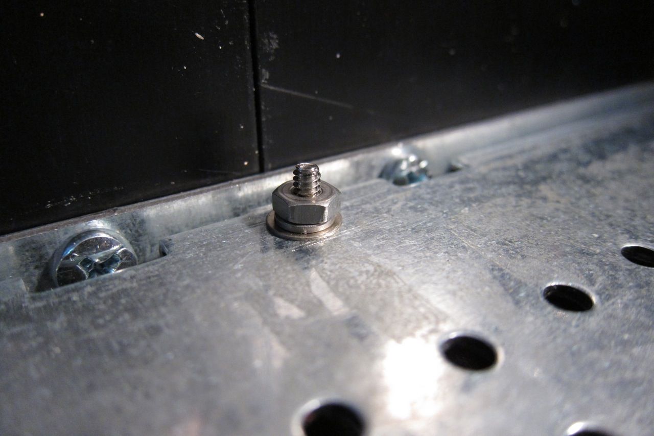
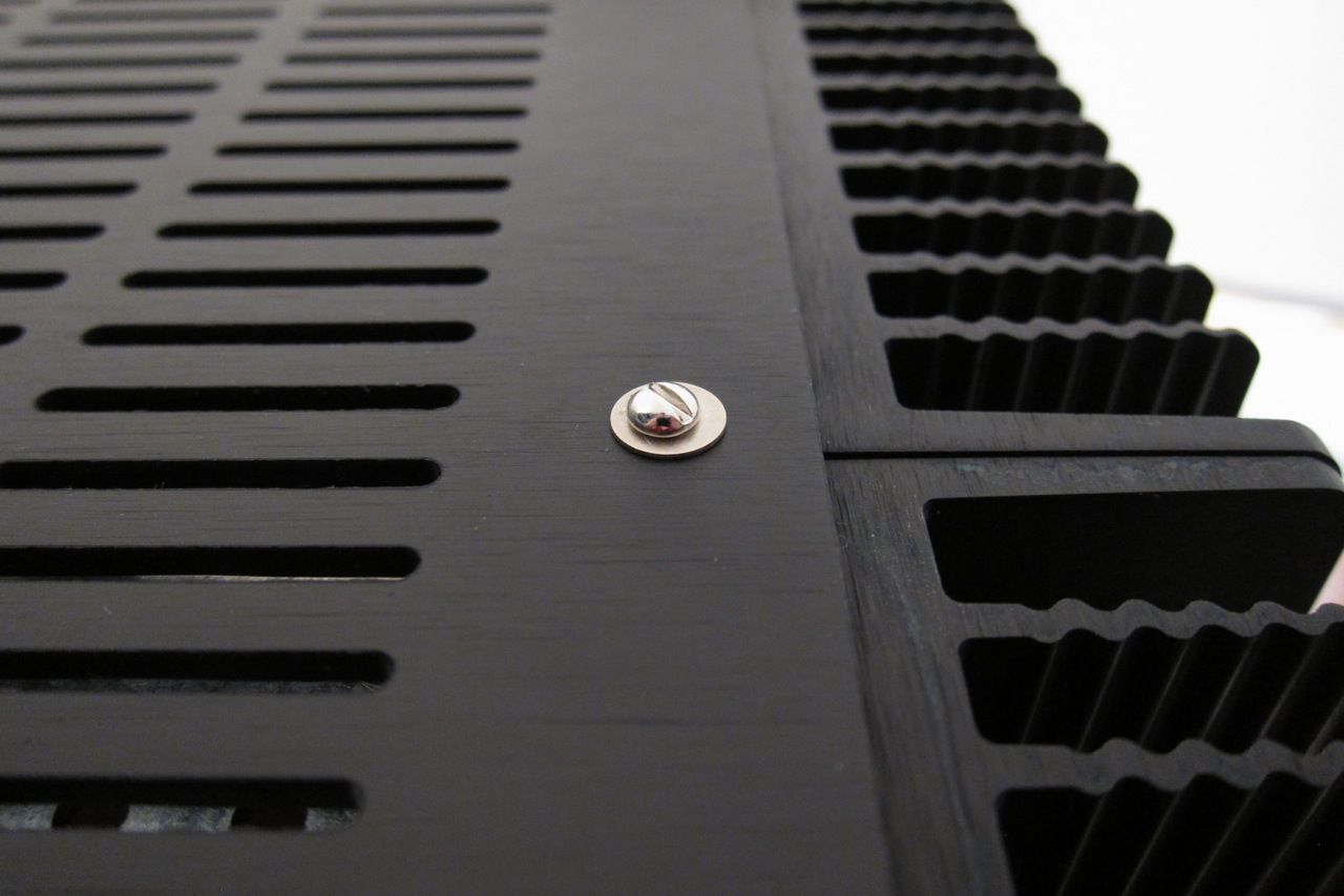
I'm not entirely sure what I was trying to show here, other than the screw and washer. It looks cool. I will keep the photo in the guide.
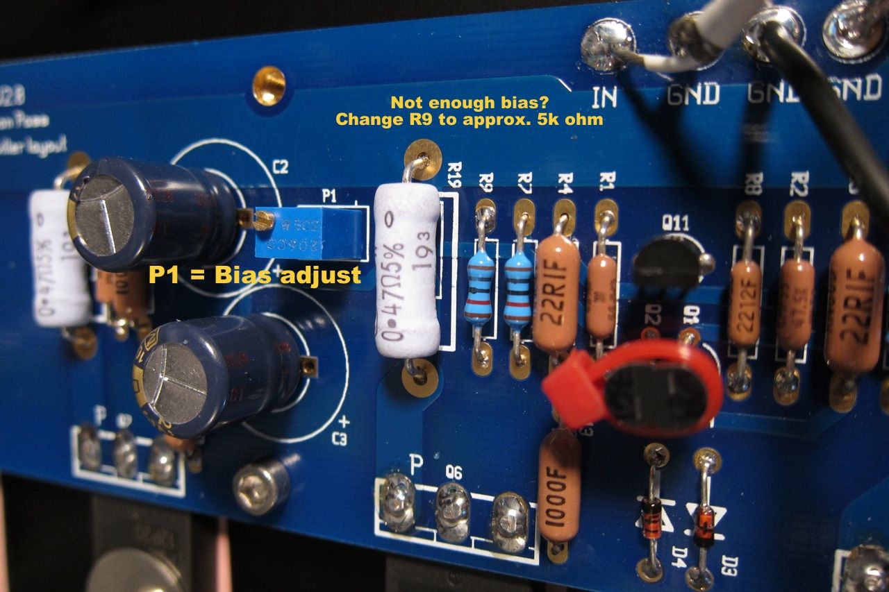
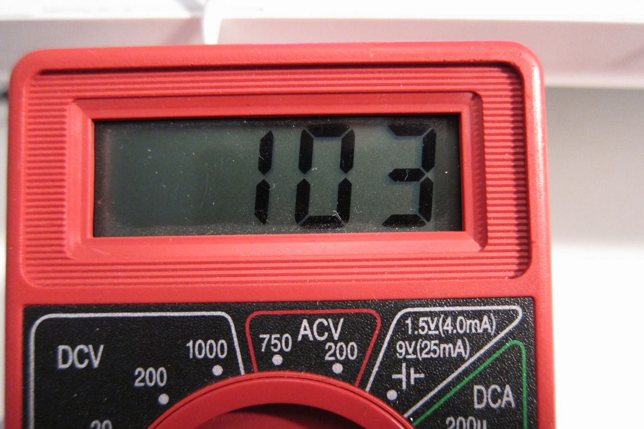
A few notes on bias -
P1 controls the bias, measured across any of the 3W source resistors. Adjust for 0.13v when it's cold, and watch that it doesn't get higher than 0.2v once it's up to temperature in about an hour. Adjust for 0.2v when hot.
P2 is used to adjust the DC offset on the output to zero.
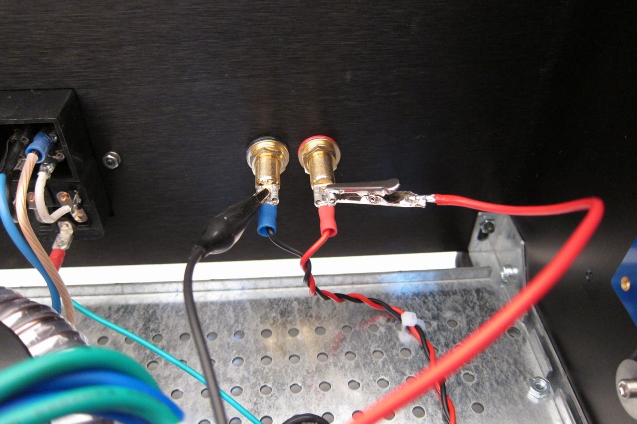
Attach a DC voltmeter across the speaker outputs to measure offset.
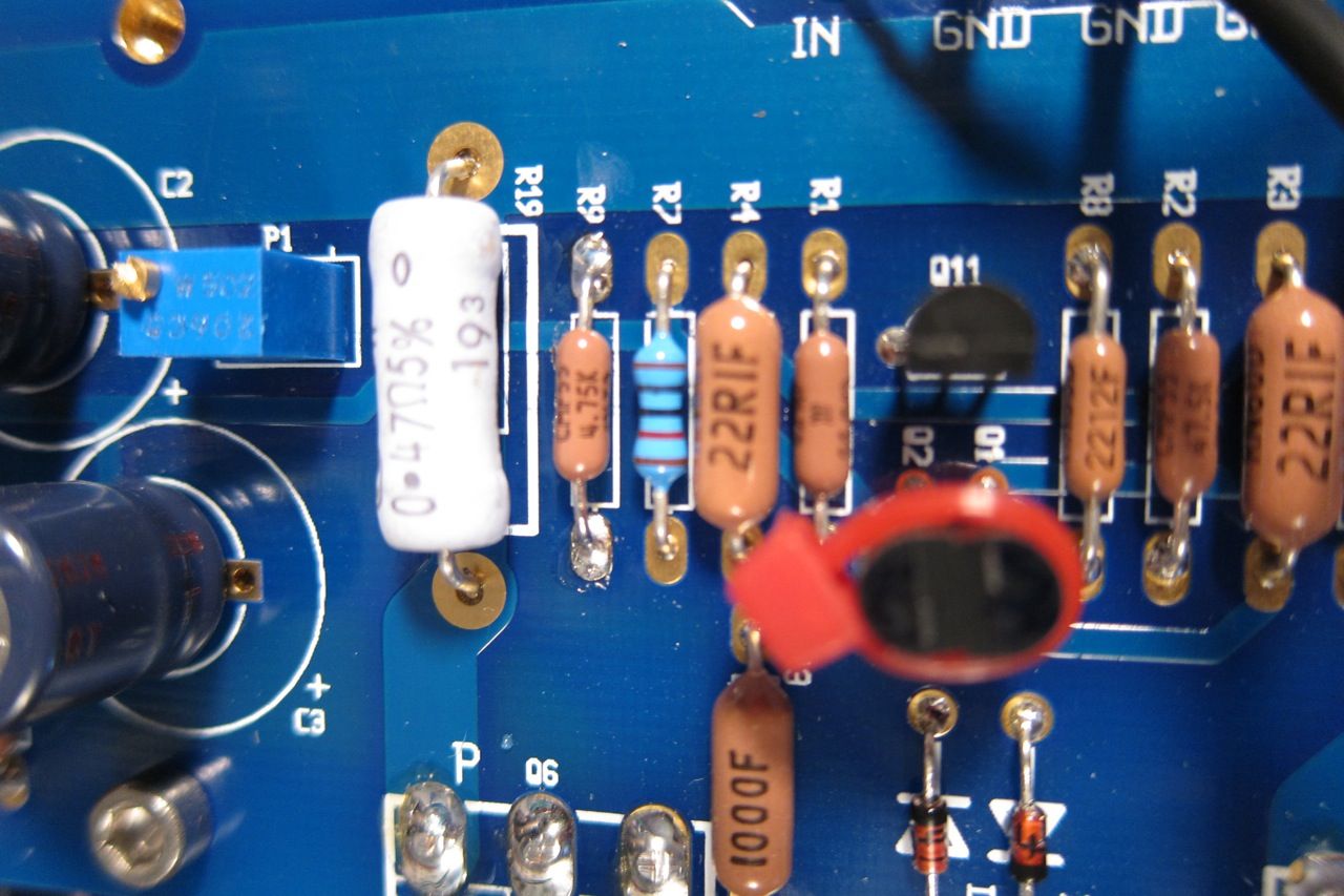
If you find that the P1 doesn't have enough range, I.E., you can't turn it up enough, replace R9 with a smaller resistor, I used 4.75K and it works well.
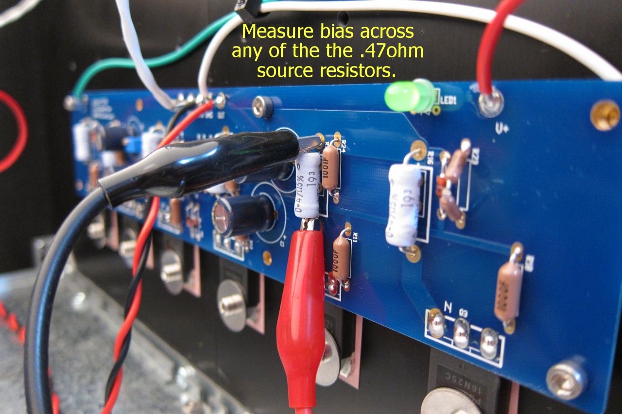
Connect a voltmeter across any of the source resistors. The outboard ones are easier to clip across.
Adjust for about 0.13v cold, and once the amp is up to operating temperature, trim for 0.20v - It takes a long time to warm up, take your time.
Adjust P2 for zero offset, then re-trim P1
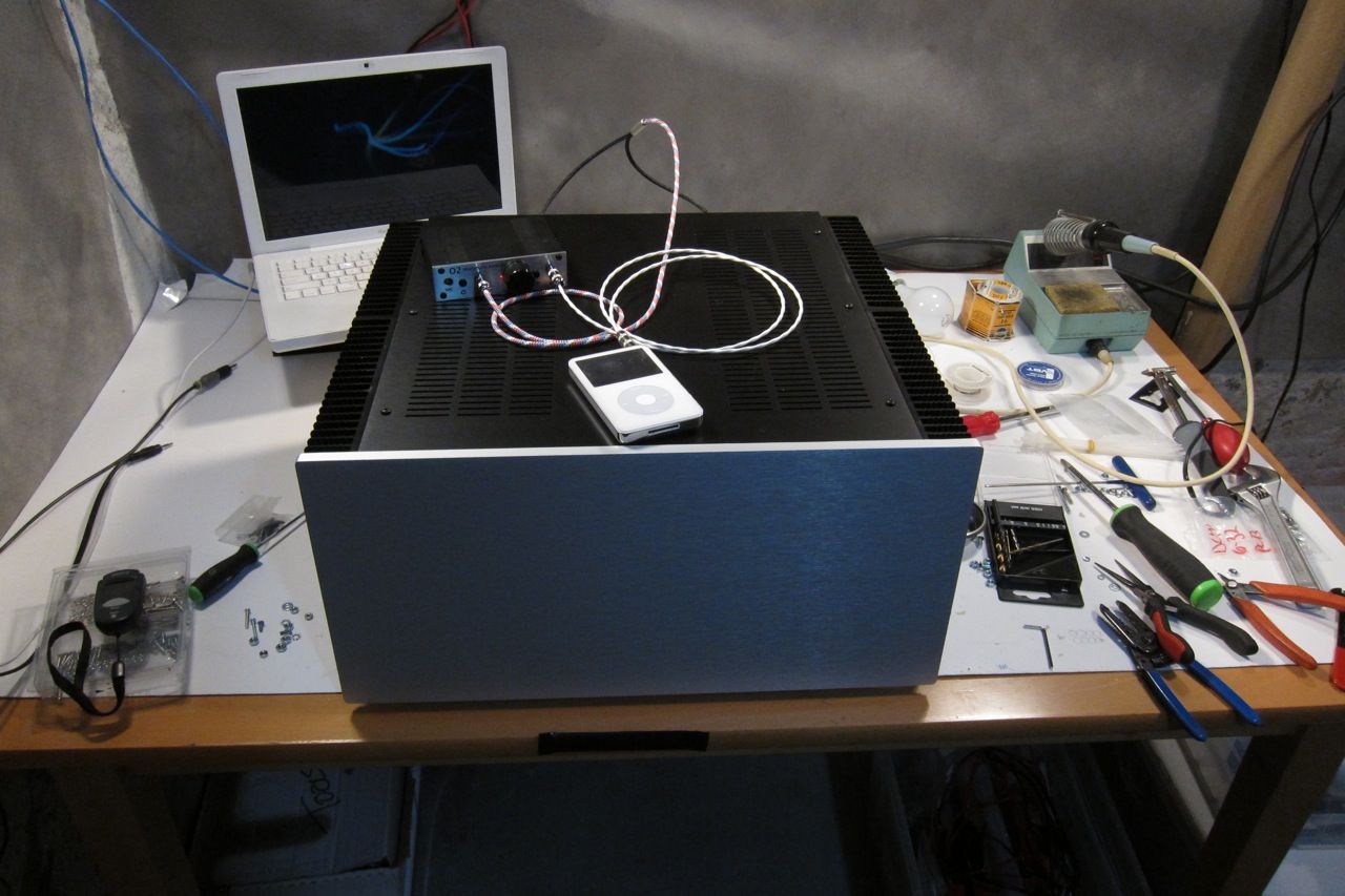
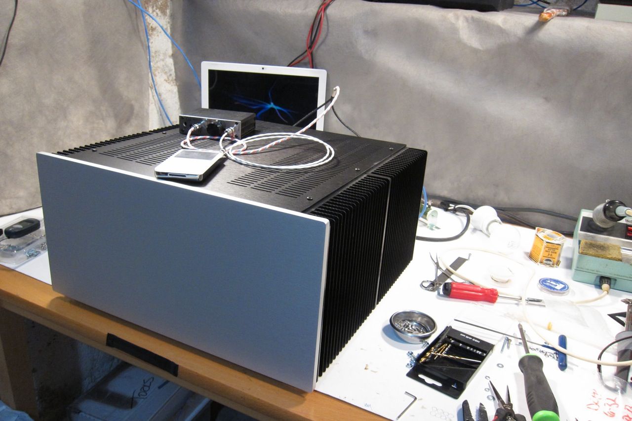
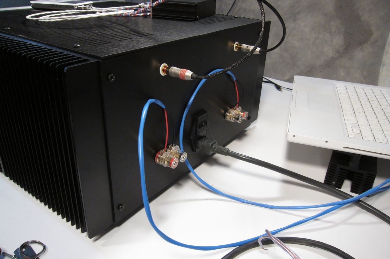
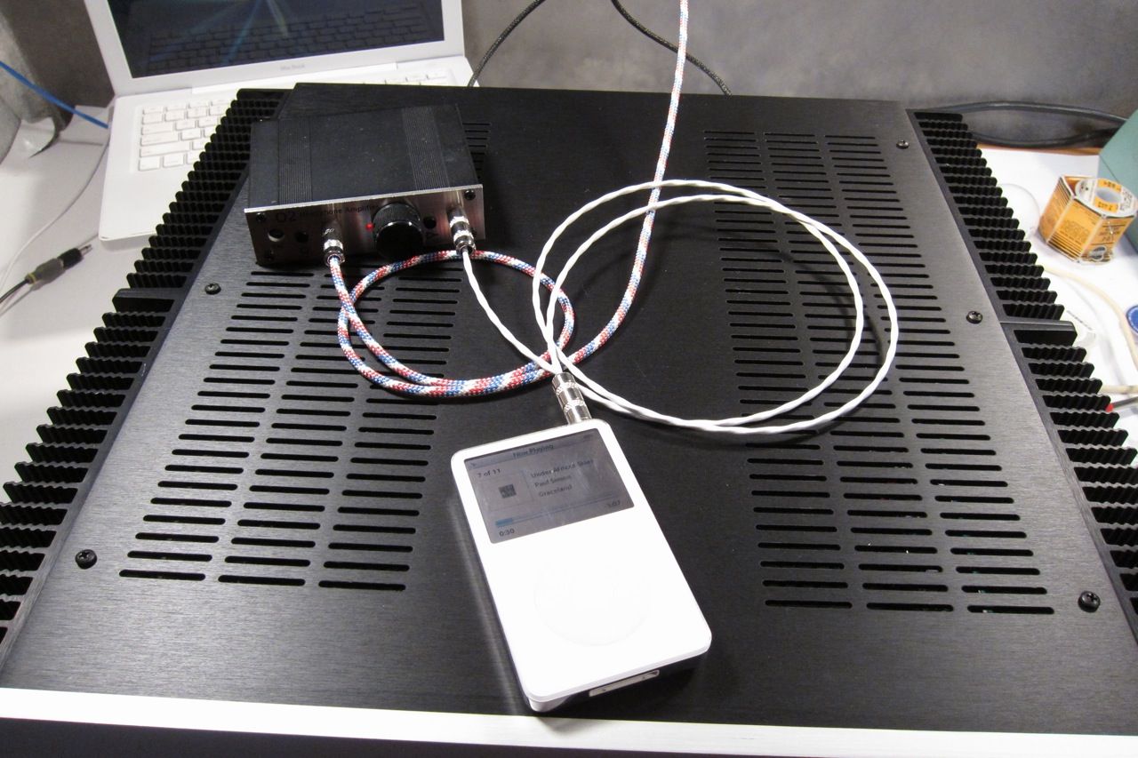
Here is a photo of it all connected and working -
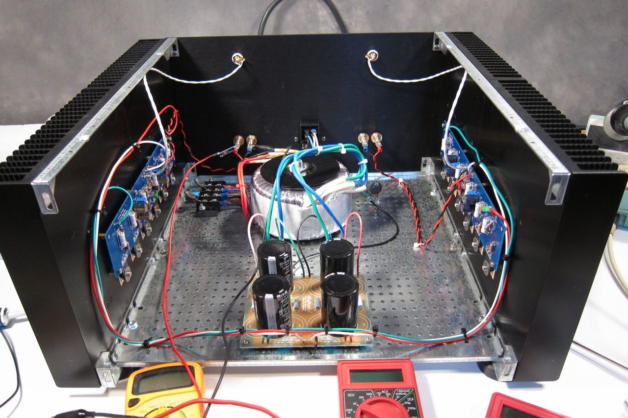
I'm driving the F4 with an O2 Headphone amp sourced from an iPod; Driving 85.5db speakers. Although it is a small room, it gets louder than I want to listen. It still can't drive it to clipping, but it does get really, really loud.
One thing worth mentioning, and it speaks very highly to the quality of the amp, is that it is completely non-fatiguing, and more interestingly, very easy to listen to turned up too loud… I don't realize how loud it actually is sometimes. Complete transparency is a word used a lot when describing this amp - but I have to agree. It's fantastic!
Please comment away if you desire.
Also please feel free to ask any F4 questions here, and if you would like to post photos of your F4 completions, old or new, please do!
This is a fantastically good sounding amp - read more about it here before staring;
https://www.firstwatt.com/wp-content/uploads/2023/08/prod_f4_man.pdf
The thread at DIY audio -
http://www.diyaudio.com/forums/pass-labs/97540-f4-power-amplifier.html
And this the the corrected schematic (The schematic in the Firstwatt article has a typo, also this one agrees with the PCB)
Here you will find a build guide for the Pass / Firstwatt F4 power amplifier using PCBs and chassis from the DIYaudio store.
The 5U 'BIG Amp Chassis' is shown, because that's the one I have. It will fit comfortably in a 4U 'Jack of all chassis' and have enough heatsink as well.
~~~~~
There are plenty of places that you could start, but for the sake of illustration let's begin with the heatsink assemblies -
This is the heatsink(s) from the 5U 'BIG Amp Chassis' It has a mirror-imaged set of pre-drilled heatsinks and brackets to hole them together and make a mounting point for the rest of the enclosure. The 4U is similar, but the heatsink is a single piece.
This build will also utilize the 'DIY friendly' baseplate, here shown with the feet and hardware, and also the heatsink's brackets.
An externally hosted image should be here but it was not working when we last tested it.
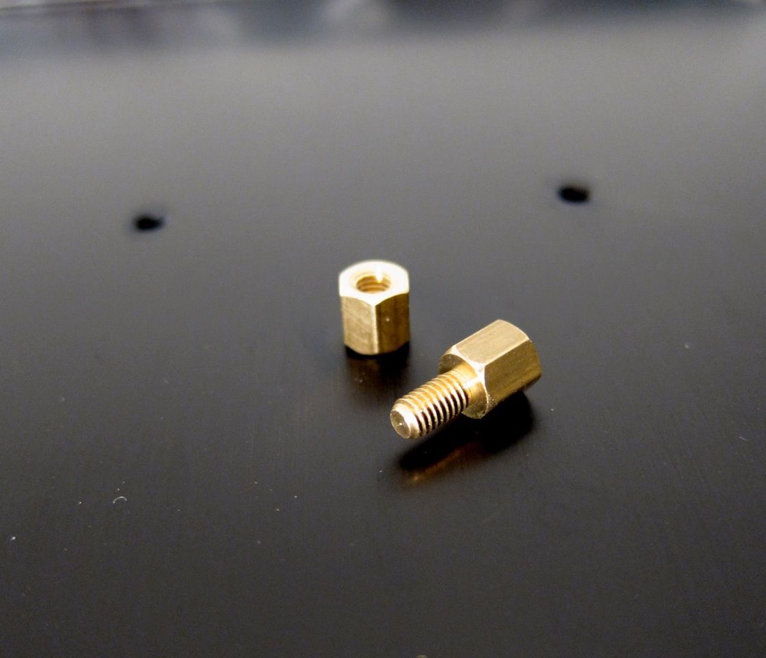
There is a hardware package available for the pre-drilled back and heatsinks, including input and output jacks, IEC module, and hardware for the PCB and heatsinks.
The contents of the hardware bag.
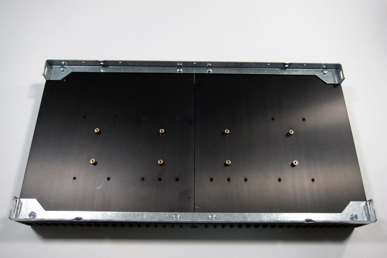
Using the brass PCB standoffs, install them into the PCB mount holes as shown, to get the following pattern;
Now there is a place to mount the amplifier PCB
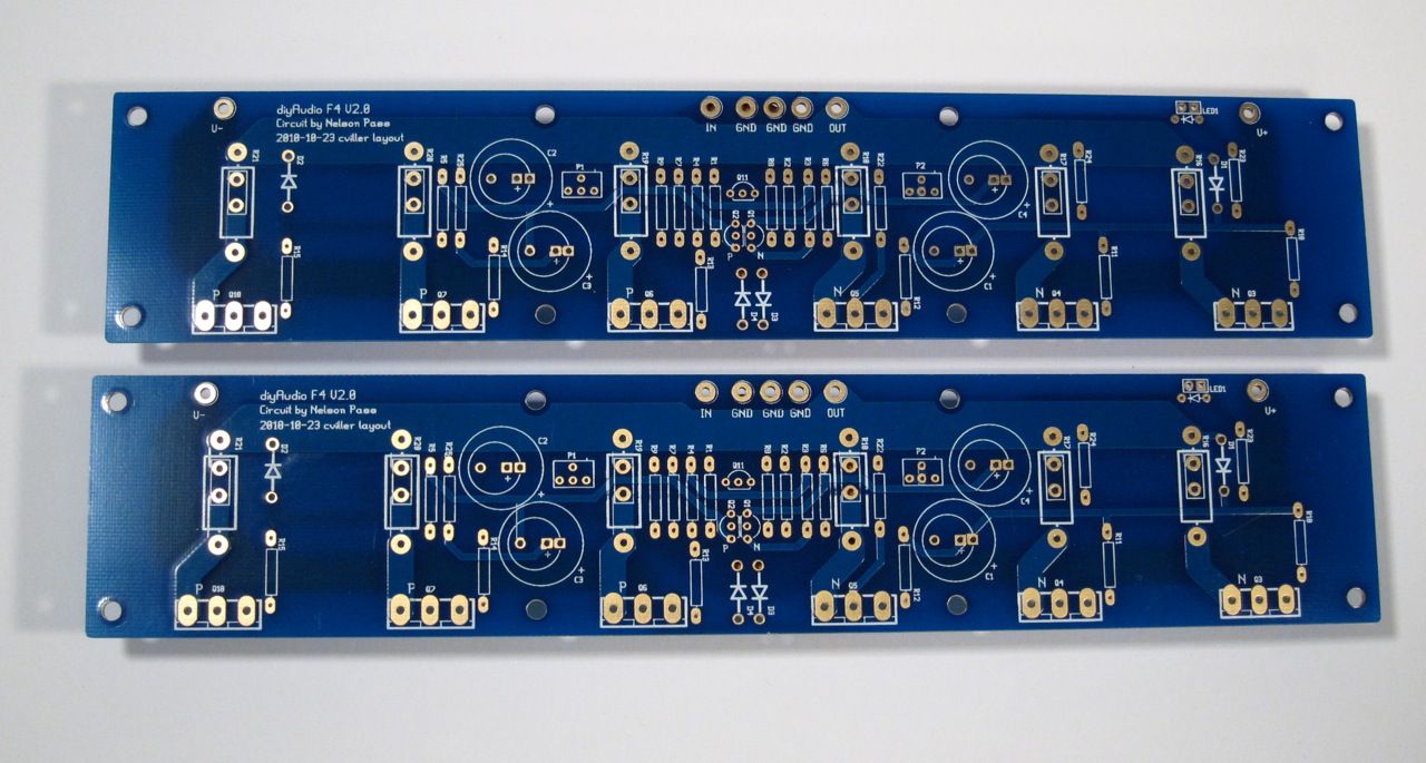
Speaking of PCB, it's a very nice layout, plenty of room, and the ability to use many sizes of resistors and caps. This is the front.
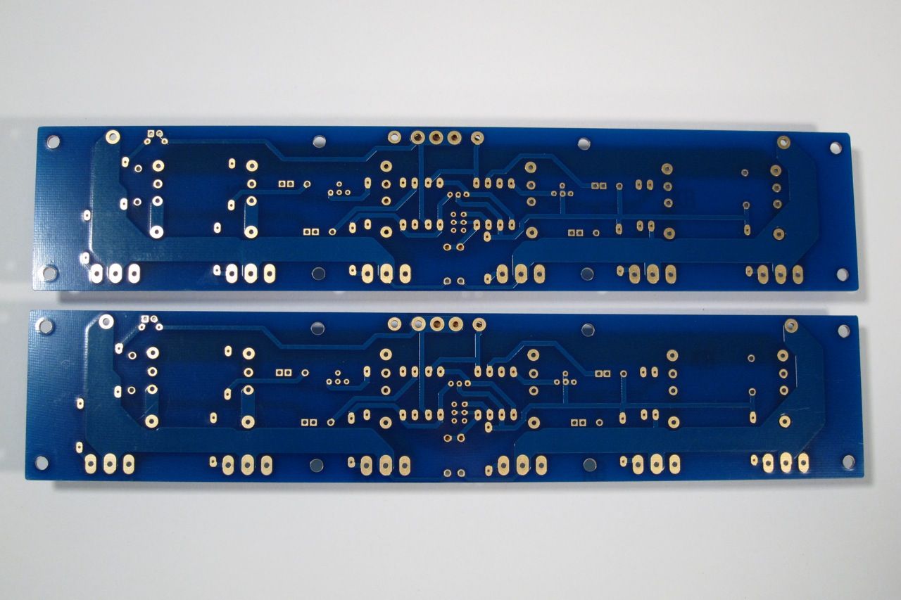
Here is the back.
Stuffing the PCB should be done in the usual order, from smallest device to biggest - so that would be diodes and resistors first.
Of note, I got the bigger (Dale/Vishay RN60) resistors to see how they would fit on the PCB. They are the size of the PRP resistors that are quite popular amongst the fancy parts crowd. They are great everywhere except the row flanking the small transistors right in the middle. They don't fit there side by side. You could mount them soldier style, or just mix in a few smaller resistors like I did. Or just get RN55's. They are the smaller size.
Pots and transistors next. (yes, I didn't stuff the input pair when the photo was taken…)
Ah, there they are.
The ziptie is just to help their thermal tracking.
And finally the capacitors.
There is a top and bottom to the Universal Mounting Spec holes, the board mounts as shown
I find it helpful to bend the leads of the transistors first, and mount them (a little bit loose) to the heatsink.
Like this
And then mount the PCB. You can snug all the screws down and then solder and trim.
Ok, now lets move on to the Power Supply.
Here is a photo of the PSU board, I am going to use integrated bridge rectifier blocks, so you need to remove the part of the PCB that mounts the diodes. The new PCB, not quite yet available at the time of this writing, will have a similar feature with the diodes, as well as room for more/bigger capacitors.
As always, stuff the small components first - the light blue resistors are the filter resistors, the darker ones with the teflon are the bleeder resistors, and the small ones are for the LEDs.
This PSU board is the exact same DIYaudio PSU board, just without the top blue soldermask.
This shows the INPUT edge (from the diode bridges)
The capacitors are Panasonic T-UP 33,000uf 35V
Connecting the bridges to the PCB
This is the OUTPUT edge of the PSU - the colors are
Red V+
White GND
Green V-
The black connects the PSU GND to the CL-60 to the chassis.
The wiring from the PSU to the amp PCB is clearly shown.
Here you can see the bridges with the wires attached from the transformer secondary. Remember that the green attached to a bridge must have continuity with the blue attached to the same bridge. (As it's the 2 ends of the same piece of wire)
As long as were are tailing about the transformer, here is a photo of the terminal block shown wired for 120v. The Blur lead is the AC Live, and the clear the AC neutral. The reds and blacks are the transformer primaries.
Transformer is an Antek 400VA 18v+18v, part number AN-4218.
The last bit of the PSU wiring is the chassis connection, the black comes from the PSU GND, and the green is the AC safety earth.
The AC to primary wiring confuses everybody, so;
Let's look at the PSU schematic just to make sure everything is OK... Remember that I am wiring it for 120v operation, so the transformer primaries are in parallel. People wiring for 240 with a transformer like this, please ignore.
Notes in red are mine.
Look at the connections of the transformer primary, through the thermistors and line cap, to the mains.
Hot AC is connected to the "120" (which in my case is the red leads on the primaries) One red primary is connected to AC hot through a thermistor.
Neutral AC is connected to the black "0" leads, one of which is connected to the AC through a thermistor.
AC Hot and Neutral have a cap across the leads.
So, yes, the AC will be connected to the center 2 posts, which is across the cap.
(This photo lifted from my F5 thread, but it's the same PSU…)
Left to right we have post 1, 2, 3, 4
POST 1 - Transformer primary 'B 0' which will be connected to AC Neutral at post 2, through the thermistor between post 1 and 2.
POST 2 - AC Neutral in (not shown in photo), connected to Transformer primary 'A 0" , a thermistor to post 1, and a line cap to post 3
POST 3 - AC Hot in, connected to transformer primary "B 120", thermistor to post 4, and line cap to post 2
POST 4 - Transformer primary "A 120", connected to AC Hot through the thermistor to post 3
If you look at the red and black wires in the photo you will see that the Mains AC must to pass through a thermistor to connect to each of the 2 primaries. And that is the point of them, to keep inrush under control during powerup.
Ok!
Now we need to put everything together -
But first a bit more mechanical assembly.
This is the pre-cut back plate and the thick front plate.
Gather and mount the IEC plug.
The speaker posts.
And the RCA jacks.
Note that the shoulder washer goes on the inside, so the metal of the chassis doesn't touch the metal of the jack. There is a similar washer on the speaker posts.
The inside of the back panel.
And the outside. Looks good, yes?
The IEC module is wired as shown. This will switch both the Live and Neutral. The blue (live) and clear (neutral) go the the wiring block with the thermistors, cap and transformer primaries.
The amp PCB completely wired.
A bit closer.
The top connections labeled.
This happens to be the other channel, but the connections are all the same.
Remember that V- / GND / V+ is always left to right as you are looking at the format of the PCB
I'm not entirely sure what I was trying to show here, other than the screw and washer. It looks cool. I will keep the photo in the guide.
A few notes on bias -
P1 controls the bias, measured across any of the 3W source resistors. Adjust for 0.13v when it's cold, and watch that it doesn't get higher than 0.2v once it's up to temperature in about an hour. Adjust for 0.2v when hot.
P2 is used to adjust the DC offset on the output to zero.
Attach a DC voltmeter across the speaker outputs to measure offset.
If you find that the P1 doesn't have enough range, I.E., you can't turn it up enough, replace R9 with a smaller resistor, I used 4.75K and it works well.
Connect a voltmeter across any of the source resistors. The outboard ones are easier to clip across.
Adjust for about 0.13v cold, and once the amp is up to operating temperature, trim for 0.20v - It takes a long time to warm up, take your time.
Adjust P2 for zero offset, then re-trim P1
Here is a photo of it all connected and working -
I'm driving the F4 with an O2 Headphone amp sourced from an iPod; Driving 85.5db speakers. Although it is a small room, it gets louder than I want to listen. It still can't drive it to clipping, but it does get really, really loud.
One thing worth mentioning, and it speaks very highly to the quality of the amp, is that it is completely non-fatiguing, and more interestingly, very easy to listen to turned up too loud… I don't realize how loud it actually is sometimes. Complete transparency is a word used a lot when describing this amp - but I have to agree. It's fantastic!
Please comment away if you desire.
Also please feel free to ask any F4 questions here, and if you would like to post photos of your F4 completions, old or new, please do!
Last edited:
https://www.passdiy.com/project/preamplifiers/b1-buffer-preamp
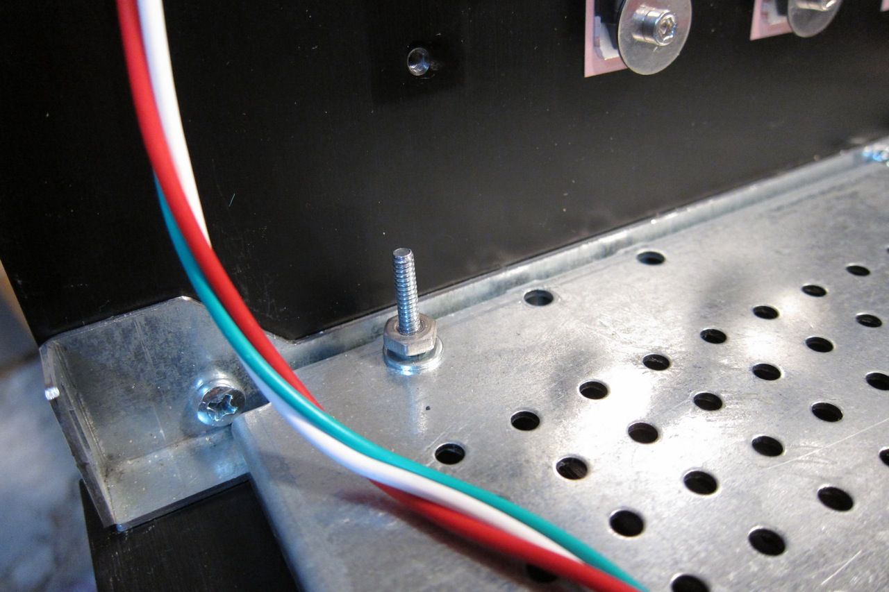
The eagle-eyed among you noticed that I had the perforated baseplate installed upside-down, so I needed to flip it over and mount it so the screwheads under the steel perf would not touch the actual baseplate.
The provided hardware is a bit short, so I needed to improvise - this is DIY, after all, so no big deal.
You can see here the perforated baseplate installed correctly.
When searching for screws, they always come in 2 lengths - too short and too long...
But those screws on the 4 corners do need to be longer than the center screws because the chassis feet are mounted with them.
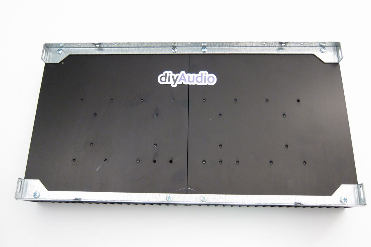
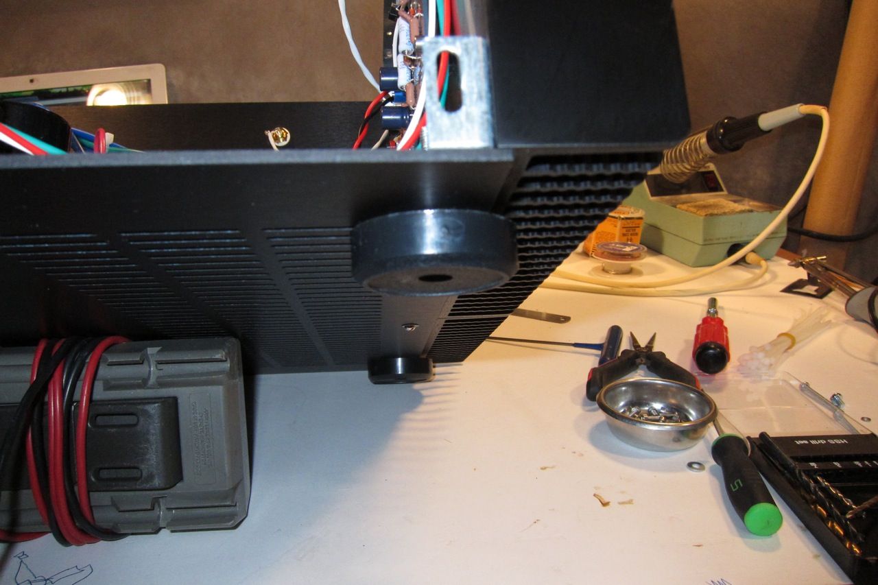
Amp bottom
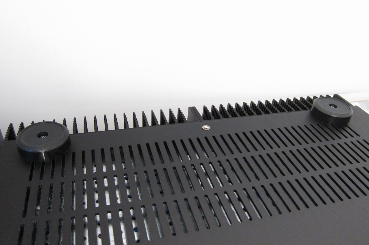
When complete, each side of the amp bottom should look like this.
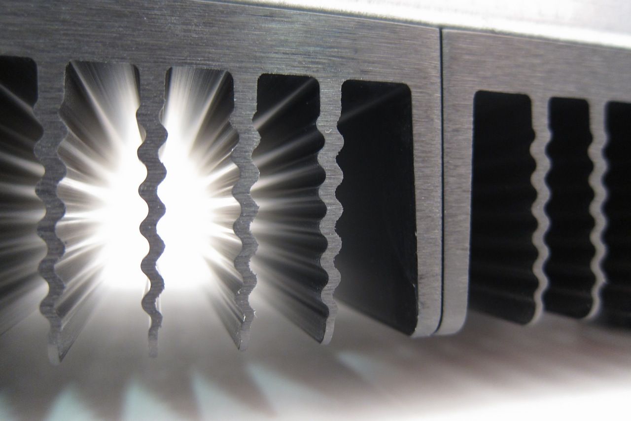
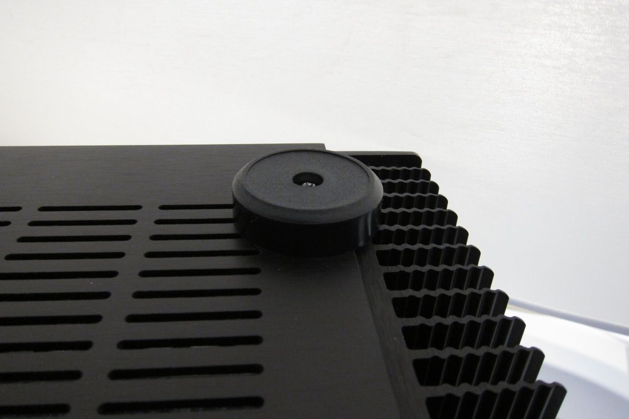
A neat photo highlighting the extrusion profile of the big heatsinks.
That completes it, the chassis is quite simple to assemble, and the pre-drilled back makes things really simple.
The amp goes together with very little effort -- it's a rewarding project.
You can also see in these photos that the 5U 'Big Amp Chassis' is, in fact, as advertised, being quite enormous.
I used the 5U because I had it, and it will be used for a number of these guides. The 4U 'Jack of all Chassis' would be plenty for this amp.
For now I am driving the F4 with an O2 Headphone amp, as it is the only 'preamp' I have that can swing enough volts (7) to give real volume, although not to clipping. Still, has enough drive for my current setup, so I'm not wishing for something else. It also sounds fantastic. Seriously.
An ImPasse will be built to drive this amp, and I am also very interested in the Pumpkin / Shunty.
So how does it sound? Well, there is not a lot to say because it's so incredibly neutral, it sounds a lot like the O2, which is very neutral and musical itself.
I have been finding the amp extremely difficult to listen to critically and listen to the amp, as I find myself singing along to whatever I play… Every time. It's really cool.
How does it compare to the F5? That's very hard to describe - you the F5 is a fantastic sounding amp, no question. Better than any other amp I have ever built, tube or SS. It (the F5) will make you understand the whole 'Class-A' mystique, and you will be very happy that you built it, because it delivers on it's promises. It truly is a great amp and a great design.
The F5, when compared to the F4 is, in my opinion, is a bit boring. The F4 is that good. . But remember it comes at a price, specifically that you will likely need a dedicated preamp for it. (Or you could bi -amp it with a flea-powered tube amp, but that's a different story. See the manual for more info.)
Some interesting measurements concerning bias levels -
Here are some quick and dirty measurements I did looking at various levels of bias on the F4. ( +/- 22.5V rails )
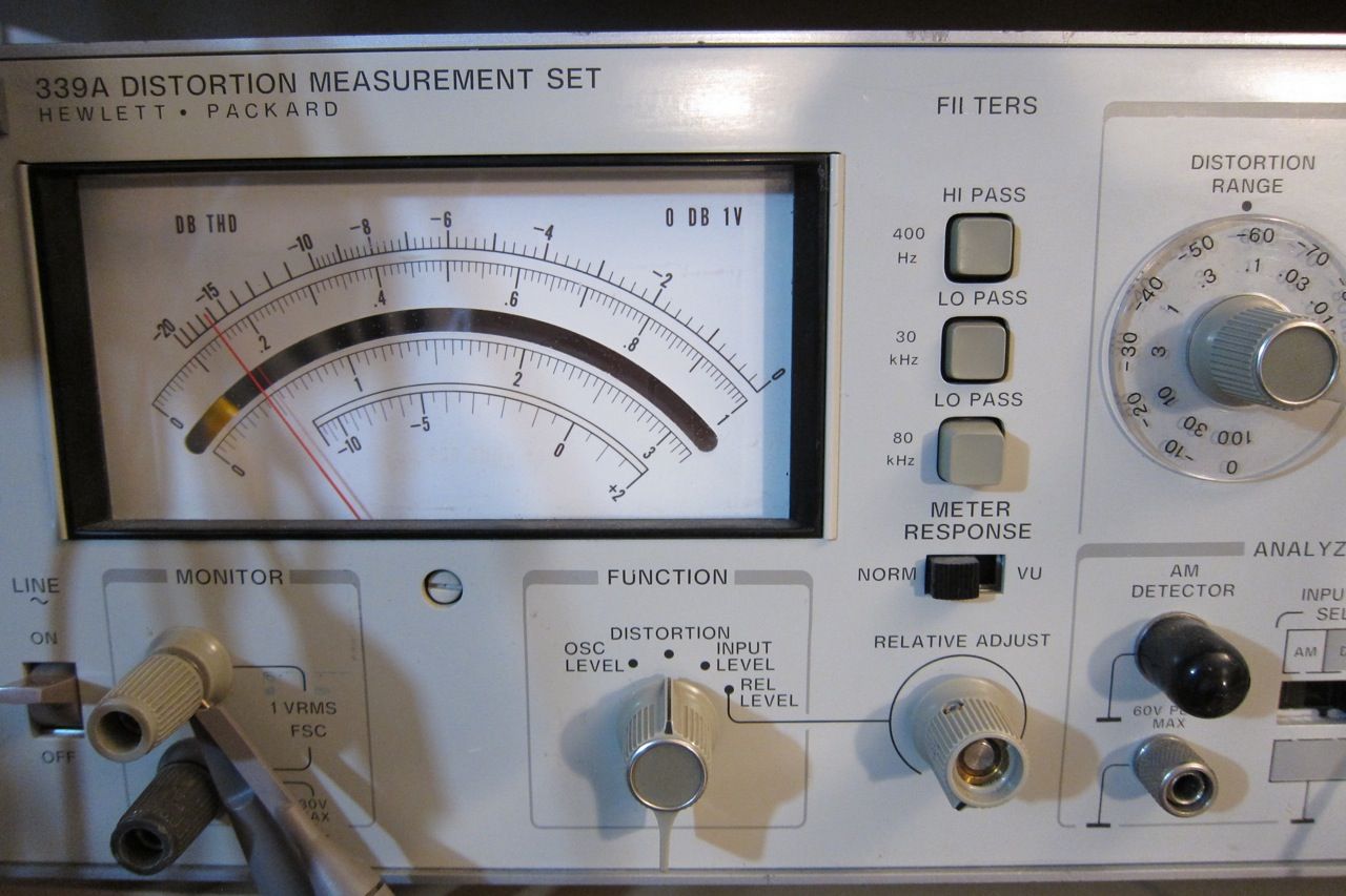
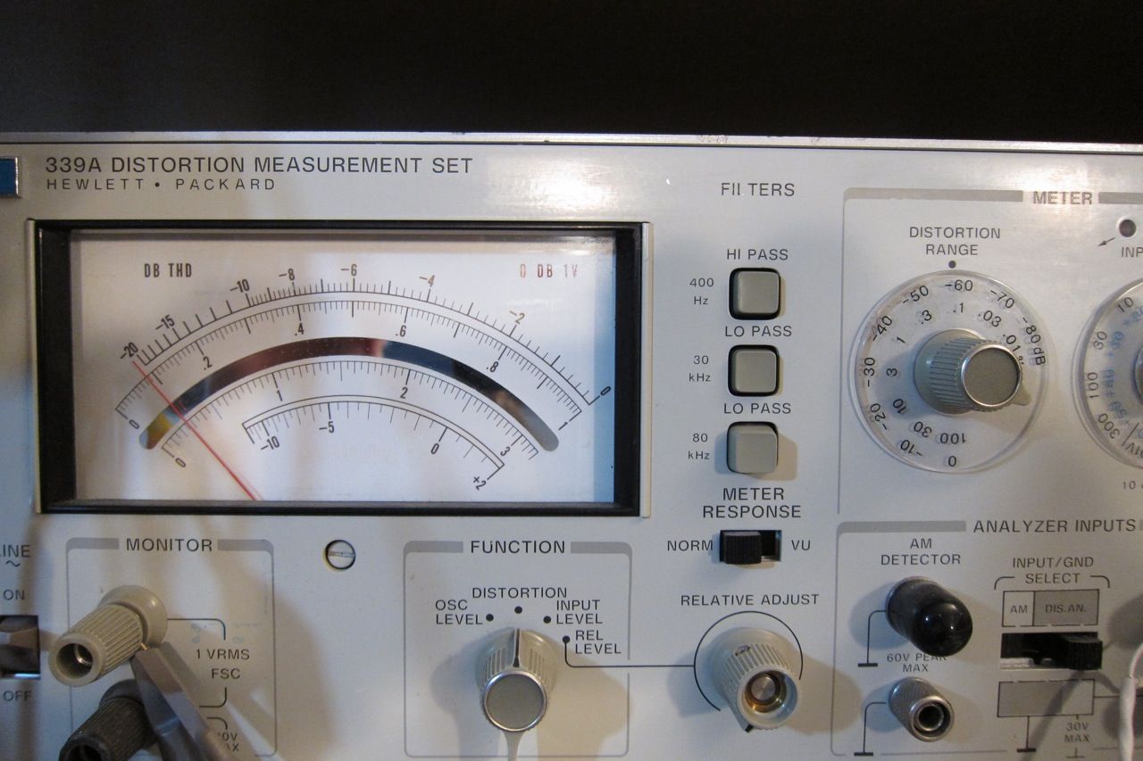
The conditions are, amplifier to normal temperature, one channel driven (because I cant read 2 at once), input to amplifier 3V 1.1kHz sinewave from 339A, distortion read across 4ohm 100W dummyload resistor, oscilloscope and FFT connected to HP 339A monitor, which was outputting the residual distortion waveform.
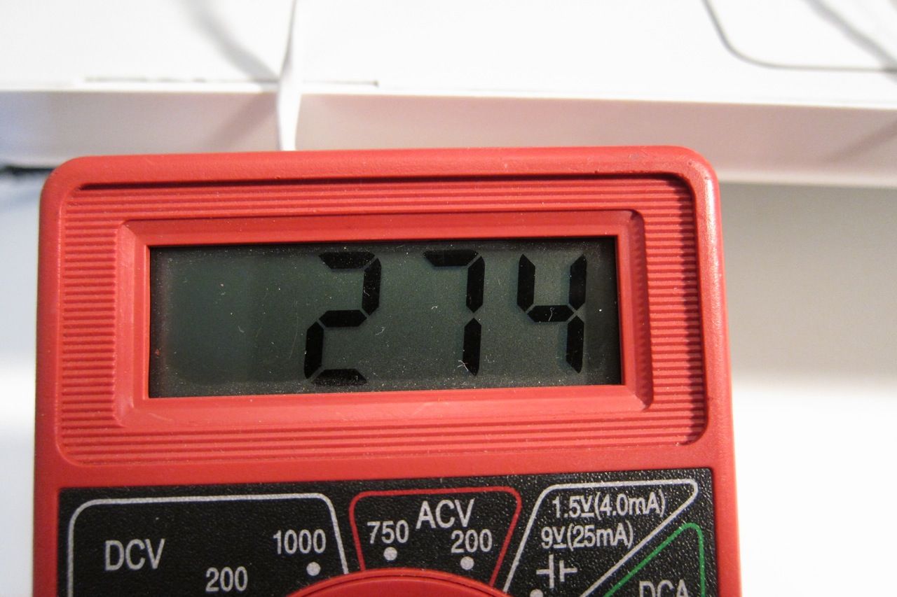
Bias measured across a .47 source resistor. (This is 1/2 the normal level, for illustration's sake)
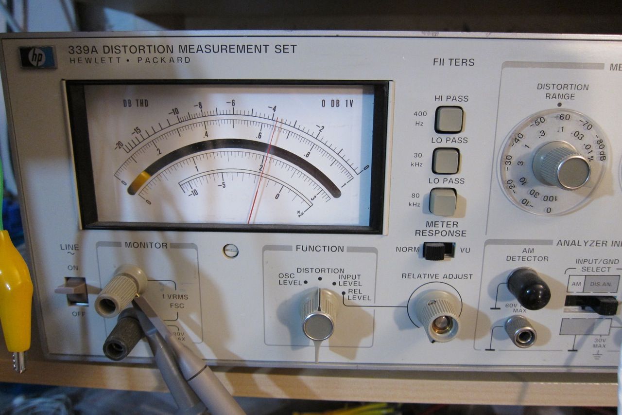
Distortion (Meter is set to the .1 scale, look at the arc above the mirror, here showing .065%)
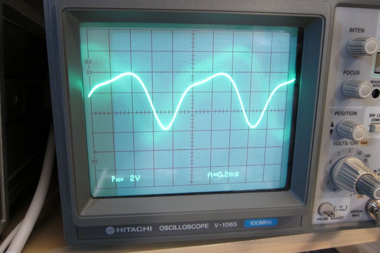
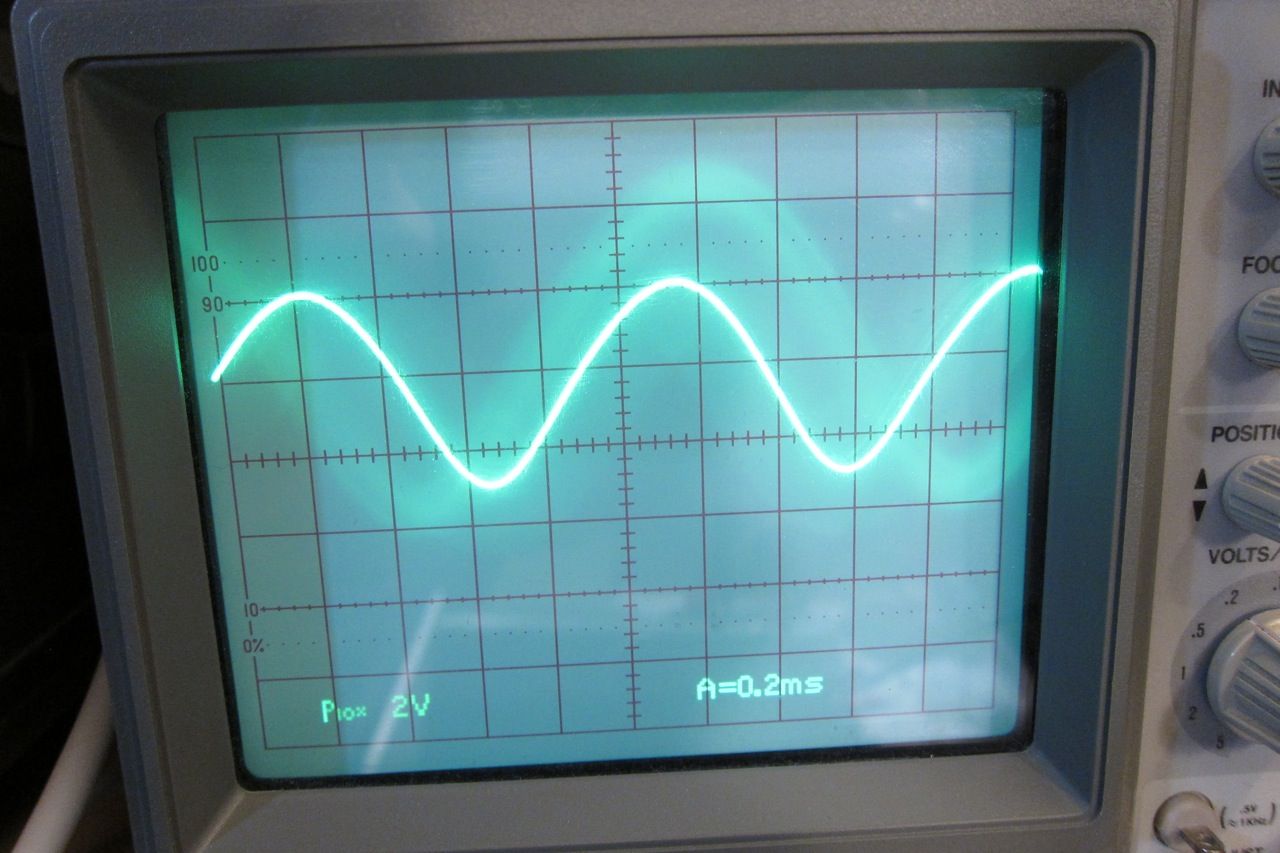
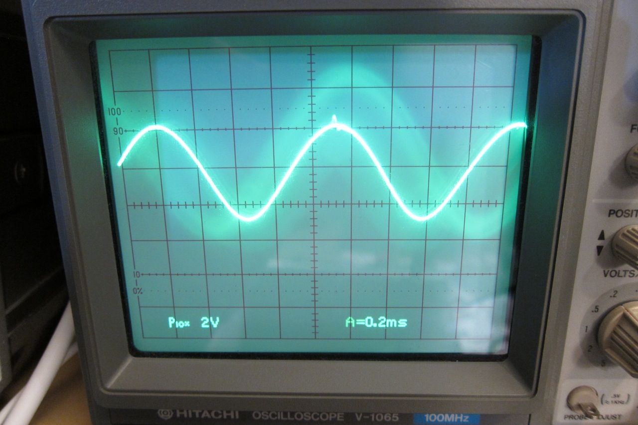
Here is the shape of the distortion residual. (No distortion would look like a perfect sinewave.)
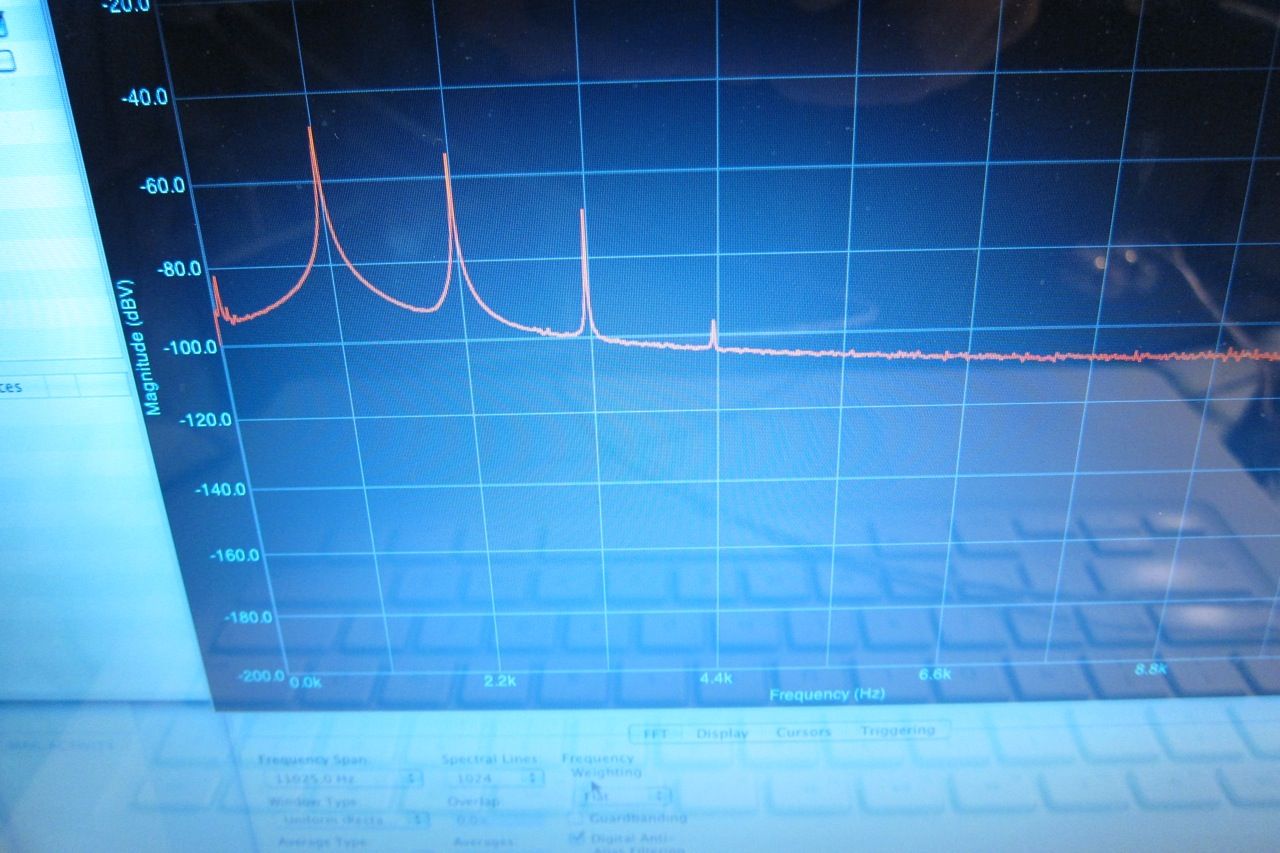
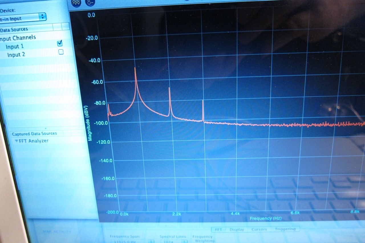
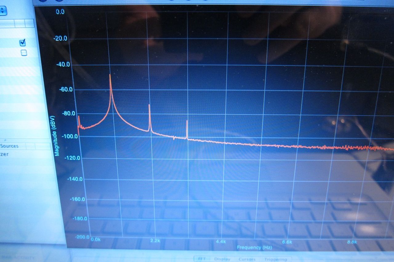
FFT of the distortion residual. (please excuse the photo of the screen. The next time I do this I will get screenshots.) The 1st peak at 2.2k is the fundamental. (2.2k chosen as it aligns with the gridlines. ) Looking right, he 2nd peak is the 2nd harmonic, the 3rd peak the 3rd harmonic, and the 4th peak the 4th harmonic. Higher level harmonics are not visible, as they are very small and lost in the noise.
Now let's increase the bias to the recommended amount, 200mv measured across the source resistors.
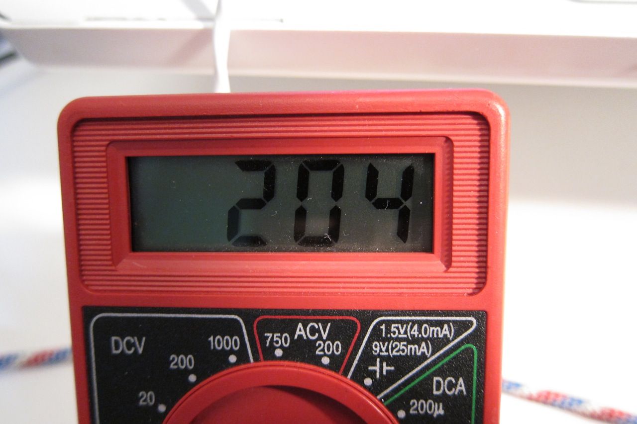
Distortion has now decreased to .016%. All that has changed is the bias. What a marked difference!
The distortion residual has lost it's humps and is looking very smooth.
The 4th harmonic is no longer visible, and the 2nd and 3rd are greatly reduced.
Increasing further -
Distortion now .08%
Residual very similar to above, but even more smooth. (A little bit, anyway…)
FFT showing the 2nd and 3rd harmonic even lower. Neat!
So the logical thing is to just crank it all the way up, right? Well, yes and no. Here are the reasons (and people with more experience please correct me if I'm wrong.)
1) Heatsink - at some point you are going to get too hot. With the 5U that wasn't an issue. A good rule of thumb is the transistors 65C max and heatsinks 55C max.
2) Bias current vs. VA of transformer. You don't want your total bias current (in watts) to be more than 1/2 or maybe 2/3 or your transformer's VA rating.
3) Transistor dissipation. Make sure you look at the datasheet for the output transistors, they all have an absolute maximum and a de-rating as they get hotter. For long life don't set more than 1/2 the max dissipation.
4) Point of diminishing returns. In this example the measured distortion continued to decrease (down to .045 or so) as bias was increased to 370mV, but the gains were very small and it would added lots of heat. The sweet spot was closer to 300mV bias.
Last edited:
😛 Awesome build. I should give this a shot - easy to build and swap out with my F5. Preamp outs on my Yamaha receiver would probably drive but the DIY Store could use a pre-amp board with some gain. 😉
I would agree with Buzz - I looked very closely at the BA3 front-end as a preamp before deciding on the ImPasse... which was decided on for a bunch of non-performance related reasons. (Although it's performance is no slouch at all...)
Specifically, I am interested in a project with an input transformer, I have a ton of very premium 6SN7 and 6DJ8, I haven't built a tube project in a while, etc...
Specifically, I am interested in a project with an input transformer, I have a ton of very premium 6SN7 and 6DJ8, I haven't built a tube project in a while, etc...
There are. BA1/2 and BA3. Both are very capable and can easily work as a preamp.
Interesting - board is $7. I have not looked the the BAs that closely. Anyone post one of those to make standalone preamp? Need to add some sort of attenuation for volume. I am sure there are a few other details.
Like anything, put your selector switch then your pot/stepped attenuator before the input of the gain stage. Easy!
PSU could be done a million different ways, choose your preferred flavor.
I would be happy to help, if you would like a nudge in the right direction. 🙂
PSU could be done a million different ways, choose your preferred flavor.
I would be happy to help, if you would like a nudge in the right direction. 🙂
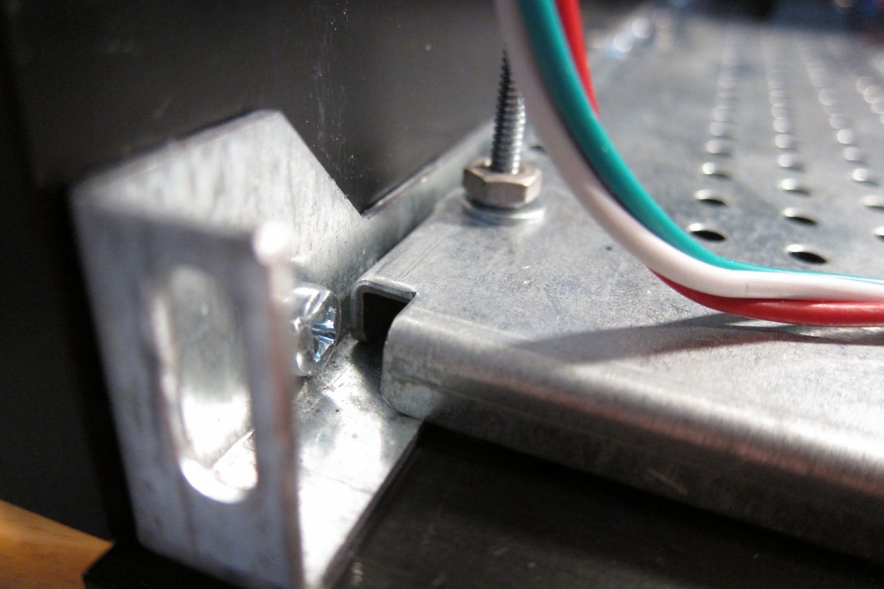
Really great pics and write-up ! I have a heat-sink question as I have not drilled my sinks yet. Could someone tell me the distance from the bottom for the mosfet bolt holes ? See pick 
Interesting - board is $7. I have not looked the the BAs that closely. Anyone post one of those to make standalone preamp? Need to add some sort of attenuation for volume. I am sure there are a few other details.
Build two F4's and go balanced with BA3 and you have something very nice. Has P3 to adjust sound to your liking. No feedback is special sound.
Fugly! tutorial 
(except fact that 4x33mF is sissy cap bank , in my book )
)
and , yes - if you turn that tech. bottom plate upside down (comparing to present position) , you'll have place for screw heads underneath
in way like you made it , screw heads are bottoming to regular bottom plate
there is a way to save what you made , without flipping that plate and making new holes - take longer M4 screws (4 pcs , which are holding tech. plate to side brackets ) , screw them to side brackets with 2 screw nuts on each , then put tech. plate on them , screw it with screw nuts
that way you'll have 2 screw nut height of clearance between tech. and bottom plates
(except fact that 4x33mF is sissy cap bank , in my book
)and , yes - if you turn that tech. bottom plate upside down (comparing to present position) , you'll have place for screw heads underneath
in way like you made it , screw heads are bottoming to regular bottom plate
there is a way to save what you made , without flipping that plate and making new holes - take longer M4 screws (4 pcs , which are holding tech. plate to side brackets ) , screw them to side brackets with 2 screw nuts on each , then put tech. plate on them , screw it with screw nuts
that way you'll have 2 screw nut height of clearance between tech. and bottom plates
Last edited:
Like anything, put your selector switch then your pot/stepped attenuator before the input of the gain stage. Easy!
PSU could be done a million different ways, choose your preferred flavor.
I would be happy to help, if you would like a nudge in the right direction. 🙂
🙂 Order complete - F4 and BA3 front end boards.
Really great pics and write-up ! I have a heat-sink question as I have not drilled my sinks yet. Could someone tell me the distance from the bottom for the mosfet bolt holes ? See pick View attachment 343260
1/3 up from the bottom is a nice place to start.
It sounds that good that I would want to get naked. 🙂 Sorry - could not resist. Not sure I quite follow. I would be using with Pearl 2/TT, CD and Sonos. If I only had a DAC or digital source I could go naked - just use the BA3 board as is between the source and F4. Use source to attenuate.You can go naked with f4 if using Ba3 FE.
Dropping the Jfet FE on F4. Basically complete BA3. You can wire F4 with switchable input so that it can be used as plain F4 or Naked F4.
(except fact that 4x33mF is sissy cap bank , in my book
It's quiet and I had it on hand. 🙂 🙂
The next DIYaudio PSU circuit board will be able to hold (8) caps with 35mm diameter - Once those are available I will make a big Brutus cap bank.
Papa uses (8) 15,000uf, so he must be sissy as well? LOL! 😀😀😀
and , yes - if you turn that tech. bottom plate upside down (comparing to present position) , you'll have place for screw heads underneath
Yes, I suppose it is upside-down... 😱
However, there are no holes drilled in it except big one for transformer, so flipping the sub-plate will actually be easy. I need to take it apart anyway to attach the rest of the chassis pieces.
6L6
Fantastic guide !!!! I will soon be assembling my Ba3B - F4 and now I have the model !!!! Thank you 😀
Fantastic guide !!!! I will soon be assembling my Ba3B - F4 and now I have the model !!!! Thank you 😀
What is the ETA for the next Diyaudio PSU board ? Here is a link for the one I have, it has the thermistor board mounted. Please tell me what you think.... See link > CRC Power Supply PCB Terminal Blocks Thermistor Are Included | eBay
- Home
- Amplifiers
- Pass Labs
- A guide to building the Pass F4 amplifier