Hey Dennis, Thanks.
No problems with cooling in the 5U.
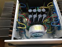
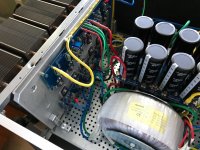
I used a 600VA with 2 X 18Volt legs Trans from Antek (AN 6218)
I stood that up with a bracket from Toriod.com L-Brackets #L-300.
I'm not by my amp right now for a picture, but it's pretty straight forward, and no drillng of holes was required.
No problems with cooling in the 5U.
I used a 600VA with 2 X 18Volt legs Trans from Antek (AN 6218)
I stood that up with a bracket from Toriod.com L-Brackets #L-300.
I'm not by my amp right now for a picture, but it's pretty straight forward, and no drillng of holes was required.
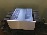
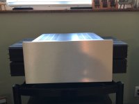
My Second Amp
Technically just my 1st amp reconfigured, as I to wanted to build a F4 Balanced amp, but in one chassis.
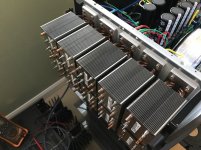
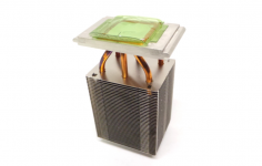
I hunted down a bunch of obsolete Dell heatsinks that I bought for almost scrap value. They were banged up and bent so I had to straighten them all by hand. But I liked them because they had 3 "U" shaped heat pipes with lots of .010 alu fins.
I machined up a couple of alu mounting plates to hold the F4 boards on one side and the heatsinks on the other. I also machined the heatsinks to mount them flat against these plates and put in the mounting holes.
I used 10 heatsinks per side. I liked the results. They move the heat very quickly.
I was able to bias each of the 4 boards to 250 mv. That keeps all the devices under 60C. -- 50-56C depending on inner vs outer placement. The heatsinks are tracking 2 to 3 degrees cooler.
The 600 VA trans is also at around 60C. I think it's struggling to keep up?
This thing is throwing lots of heat. That's OK with me as I'm Canadian, and "Winter is Coming"
Technically just my 1st amp reconfigured, as I to wanted to build a F4 Balanced amp, but in one chassis.
I hunted down a bunch of obsolete Dell heatsinks that I bought for almost scrap value. They were banged up and bent so I had to straighten them all by hand. But I liked them because they had 3 "U" shaped heat pipes with lots of .010 alu fins.
I machined up a couple of alu mounting plates to hold the F4 boards on one side and the heatsinks on the other. I also machined the heatsinks to mount them flat against these plates and put in the mounting holes.
I used 10 heatsinks per side. I liked the results. They move the heat very quickly.
I was able to bias each of the 4 boards to 250 mv. That keeps all the devices under 60C. -- 50-56C depending on inner vs outer placement. The heatsinks are tracking 2 to 3 degrees cooler.
The 600 VA trans is also at around 60C. I think it's struggling to keep up?
This thing is throwing lots of heat. That's OK with me as I'm Canadian, and "Winter is Coming"
Attachments


Wow 10 on each side! That's really nice.
Off topic a bit, and guessing you looked into this; at some point as the fins get closer together they restrict the airflow - do you have any idea what the trade off is?
I'm guessing these originally came with a fan?
What is the total dissipation?
That is very nice, thanks for sharing
Off topic a bit, and guessing you looked into this; at some point as the fins get closer together they restrict the airflow - do you have any idea what the trade off is?
I'm guessing these originally came with a fan?
What is the total dissipation?
That is very nice, thanks for sharing
Last edited:
These are heatsinks that came inside the Dell Optiplex GX280 computers, so there was a shroud and fan to maximize cooling. I looked around for something using heat pipes and a large surface area utilizing alu fins. And I didn't want to spend a lot of money on them.
For these, I couldn't find any dissipation numbers on Google, but each heatsink has 42 fins at 2.5 x 3 inches. So that's 315 sq inches x 2 sides = 630 sq inches, less the heat pipe holes etc.
The fins don't move as the alu is coated in a clad material that fuses to the heat pipes and other alu touch points as the assembly stack passes thru ovens at manufacturing. I've run the amp for several days now, and nothing has moved, it been fine.
Thanks for your interest.
Attachments
And if I am guessing accurately you are using +/-23V and 250mA bias...
6 devices per board and four boards - so this is running about 300W?
Hi BeardyWan
Yes, I believe so.
Thank you Zen Mod. I have a tube pre with, from what I understand, lot's of voltage swing but not may current capabilities, so I thought that a higher input impedance could help. I have no idea about my cables capacitance. Anyway it can be quite an interesting experimentation!
The input impedance has virtually no effect on the cable capacitance effects.Thank you Zen Mod. I have a tube pre with, from what I understand, lot's of voltage swing but not may current capabilities, so I thought that a higher input impedance could help. I have no idea about my cables capacitance. Anyway it can be quite an interesting experimentation!
It's the Source impedance that most affects the cable capacitance effects. This becomes a low pass filter, which you can use to attenuate RF interference if you know the impedances
The Receiver impedance does affect the high pass filter effect created by the DC blocking capacitor.
Question about matched pairs of 2SK170/2SJ74 for the F4 amps. I have a bunch of each of these that i bought a few years ago for the burning amps etc, they are A's . The matched pairs of 2SK170/2SJ74 from the diystore are out of stock. Should I wait for them to come back in stock or just make up pair up pairs from the A series that i have? Am I gambling on performance?
- Home
- Amplifiers
- Pass Labs
- A guide to building the Pass F4 amplifier