I use Cardas Quad myself and found the complete opposite, it leaves lots of flux gloop behind. curious.
Probably not the same Cardas solder fusion temperature check with 6L6.
Isopropanol is the way to go, together with toothbrush
Yes Walter !
I promise don't confuse with personal toothbrush.
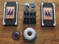
Those are huge! You can make a much bigger amplifier than an F4...
But they will work beautifully!! Power-on inrush will be an issue, make sure you use thermistors or soft-start..
22 cm = 8,6 inches high capacitor
Happyly i have batch of STM CL-60 / 5A 10 Ohm current limiters
& 0,47 Ohm 3 watts Panasonics for classic Papa psu
if all work together with appropriate bridges and Antek
i am courious to experiment with CLC and soft start.
Diy amps is passionate
and biiig Donut

Thanks Diyers

Have a nice day
Attachments

I'm the one that turned 6L6 on to Cardas Quad.
What temperature do you have set on your iron?
I have mine set to 650-670F, I have found that around that temp on my FX-888D the flux almost instantly vaporizes with very little cleanup.
Below 650 it does leave more residue.
If you cant find propanol for a reasonable price I have found denatured alcohol works EXTREMELY WELL.
It can be purchased at the home store of your choice with the thinners and stipper chemicals.
Sometimes it is called alcohol stove fuel.
It is usually above 95% pure with some water and nasty stuff added so you don't drink it.
Be careful around flames though, it burns with completely clear flame.
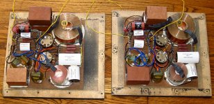
Thank you for your comments. Your photo illustrated guides were of great help during this build. Not sure I could have done it without those images!! I was concerned about the heat with the output devices in such close proximity to one another. The 12mm thick copper plate serves as a heat spreader. Even using it the output devices are at different temperatures. I feel it was worth the time to drill and tap the copper. What a pain, I broke three taps until I found one that would not clog with copper bits!
I am looking forward to the BA-3 build once the store has boards back in stock, I have been gathering parts and have constructed the Salas low voltage shunt for the power side of things.
So I will have to suffer with the Adcom pre for a while longer!!
Thanks again
David
I am looking forward to the BA-3 build once the store has boards back in stock, I have been gathering parts and have constructed the Salas low voltage shunt for the power side of things.
So I will have to suffer with the Adcom pre for a while longer!!
Thanks again
David
Success, a few stumbles, but another F4 build up and running. Very quiet. I will need the BA-3 preamp I am planning to build. The Adcom preamp is only good for 7v or so.
David (very happy)
Nice build, Enjoy!
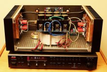
Hopefully not, but all of that heat needs to be on top! Even with the heat spreader the individual devices operate at slightly different temperatures. MY hope is by taking these extra steps, using some oversize components (500va xformer, Mundorf caps in power supply), I will improve the life of the amplifier and yes its only money and fun. I miss the days of Heathkits.
Thanks Mcandmar. Your suggestions on mounting the power supply above the transformer and using the back panel for mounting the speaker board worked well. I still have to do something with the front panel. The extra wires wrapped around one of the supports are for a front switch and LED. I thought I would let everything cook for a few days.
I agree with 6L6, the 4U case is a bit tight. Getting to the adjustment pots on the PD boards is a bit of a challenge.
I am using a pair of JBL L-220 speakers that I bought new in the 70s. I recently rebuild the crossovers in both using Mundorf, Jupiter, Sonicap, Mills and Alpha Wire components. Also got rid of those terrible connectors on the back. That ended costing me more than the speakers did originally! But hey that is what we do!
And thanks to Mr. Pass for sharing his designs, I could never afford his commercial products. It is very nice to be listening to some of his genius.
Attachments
Lap the top and bottom of the copper plate starting with 600grit wet or dry using windex as a lapping fluid, get a chunk of 1/4" glass for a flat surface and glue it to a bit of plywood for strength.
A 6x12 piece should only cost 4 or 5 bucks.
After 600g go to 1200g with windex cutting fluid.
With a bit of effort and about 30minutes of effort you should have copper mirrors and that should help your temps quite a bit.
Also i'd recommend using just thermal paste between the copper plate and the heatsink instead of the huge chunk of keratherm.
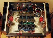
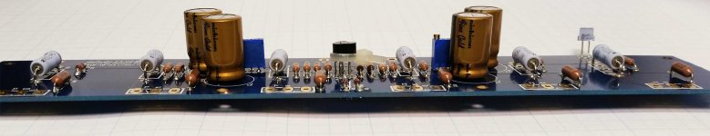
Here is my first assembled board out of four. It's been done for a bit but need to clean my workspace before I will be permitted to continue.

Hope the image sizing doesn't cause problems.
Here are some differences between this build and others - I'm using an Antec 20V 400VA transformer for each pair of boards. The PSU's were built with 35V 15Kuf capacitors. On the assembled F4 board I have 50V capacitors, but would have chosen 35V if I had planned ahead (any reason to use one or the other?). I may consider purchasing Elna 35V caps to compare the two otherwise identical amps.
Questions before I place another Mouser order or assemble the rest of the boards:
What am I likely to need to do different since I am using a 20V torroid instead of 18V?
Does the 50V vs 35V value for the capacitors make it more than simply replacing the caps should I want to switch back - another way to say - is it possible to have identical amps with the exception of the capacitors?
Length of standoffs between heatsinks and board?
Attachments
Last edited:
On the assembled F4 board I have 50V capacitors, but would have chosen 35V if I had planned ahead (any reason to use one or the other?)
Nope. That's the max voltage rating. Your build will be under either of the max voltages, so no worries.
That might be fun, and worth trying if you are so inclined, but the differences between a Nichicon FG audio-grade and a Silmic will be very, very small.I may consider purchasing Elna 35V caps to compare the two otherwise identical amps.
Nothing.What am I likely to need to do different since I am using a 20V torroid instead of 18V?
No problems swapping caps.Does the 50V vs 35V value for the capacitors make it more than simply replacing the caps should I want to switch back - another way to say - is it possible to have identical amps with the exception of the capacitors?
Thicker than the Mosfet.Length of standoffs between heatsinks and board?
Last edited:
Does the 50V vs 35V value for the capacitors make it more than simply replacing the caps should I want to switch back - another way to say - is it possible to have identical amps with the exception of the capacitors?[/QUOTE said:You can use any capacitor you have mentioned. If you want identical amps I would use identical capacitors on both. In other words I would not use Nichocon on one board and Elna on another.
Agreed best to use the same on both . Using different on two stereo units would allow you to compare thou. In the case of the F4 with no voltage gain there may be little difference . Having said that I am not sure of the test result since I have not done that yet.You can use any capacitor you have mentioned. If you want identical amps I would use identical capacitors on both. In other words I would not use Nichocon on one board and Elna on another.
- Home
- Amplifiers
- Pass Labs
- A guide to building the Pass F4 amplifier