Wow, that is a cool build. I built the BA3 as a preamp using your thread months ago and it sounds great. It has so much gain, I changed already once resistor to reduce gain, but have to be very careful with the volume control.
Think you need Santa to bring you some Chassis for Christmas!
Think you need Santa to bring you some Chassis for Christmas!
Could this amp build be too difficult for a beginner? I have made my own interconnects and that's about as far as my technical skills go. I have been waiting for the ACA kits but I don't think they are ever going to be out again. I have a Pass Aleph that is in need of an amp that can take advantage of its 20db of gain and I thought this current amp would be perfect. I also like the fact that it can be used as a mono to get 100w because I have one pair low efficiency speakers and one set of high efficiency.
You can be brutally honest. I don't want to get into/invest a project that is beyond me.
Thanks
You can be brutally honest. I don't want to get into/invest a project that is beyond me.
Thanks
enochrome.
In theory a monkey could build an amp.
normally, if you can solder and have enogh hand skill to build interconnects, you shoulkd be able to put togheter a amp module.
But knowing how the devices works and all the risks associated with electricity and asscociated troubleshooting will really set you apart.
now if you can handle a drill and other tools to make an enclosure, all it takes is patience and common sense.
or you could just order one.
plenty of info around the net on advices and such.Be sure to check it out. It's not super complicated but thwere are thing you should not pass over.
Regarding how you plan to use the amp with, i'm not sure i understand but it might just be me...
Enochrome -
Yes, a beginner could build the amp. Most certianly. Stack the deck in your favor - get the deluxe chassis, use PCB for as much as possible, etc... but yes, a beginner could make one.
Where are you located? You may be able to find somebody to help or look over your shoulder as you build.
Regarding the 100W from the F4, that requires two complete stereo amplifiers (to be run as bridged monoblocks) and a balanced output preamp with lots of gain - look specifically at the "ImPasse" and the "Pumpkin".
Check your PM.
Bridged configuration doubles the output voltage. The /ch output spec is 20V+- so bridged gets you 40V+-.
The bias of the F4 is about .43A x 3 or 1.29A total. This allows for a maximum output current of 2.58Apk for class A operation. Bridged operation provides no current benefits in this regard.
The output power spec for the F4 into 8 ohms is 25Wrms. Because it can output 20V into 8 ohms for a total of 2.58Apk, the output spec is a class A rating.
A bridged F4 outputting 40V onto 8 ohms will also only have 2.58Apk of class A usable current but that is still 25Wrms output power. It doesn't clip at 2.58A however. It reverts to Class B operation and continues to drive all the way to 40V drawing 5A into 8 ohms. That will be 100Wrms into 8 ohm speakers.
These are never ending questions but, I think this one was covered in the manual. You must also be careful with peak and rms numbers and ClassA or B operation, whenever stating numbers like these.
Rcruz,
I have not tried every amp out there,but my guess is that
lsk pre http://www.diyaudio.com/forums/pass-labs/244106-lsk-pre-baf-2013-a.html
and f4 would be hard to beat.
i m currently experimenting using a phase splitter to run balanced f4 and while i m not done tweaking, it sounds promising.
I have not tried every amp out there,but my guess is that
lsk pre http://www.diyaudio.com/forums/pass-labs/244106-lsk-pre-baf-2013-a.html
and f4 would be hard to beat.
i m currently experimenting using a phase splitter to run balanced f4 and while i m not done tweaking, it sounds promising.
Pidesd,
I am also working on a "phase splitter" driven balanced F4.
I have some surplus input transformers that have a CT on the secondary.
I rigged up one to make my stereo F4 a balanced mono and I was able to get 35W out to an 8Ω load with 580mV into the frontend of my Aikido.
I have no doubt that with a 2V input signal I should be able to get a full 100W from this beastie.
A bridged F4 outputting 40V onto 8 ohms will also only have 2.58Apk of class A usable current but that is still 25Wrms output power. It doesn't clip at 2.58A however. It reverts to Class B operation and continues to drive all the way to 40V drawing 5A into 8 ohms. That will be 100Wrms into 8 ohm speakers.
Duh -- you're absolutely right, sorry about the confusion.
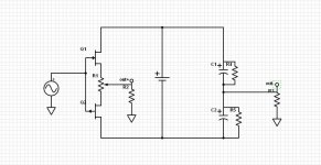
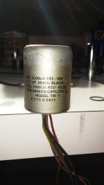
I'm using old transformers from some tube monoblocks that would have cost at least a grand to rebuild.
They are 10k:50k with a CT that isn't shown on the can but it is there on the application schematic and there is a wire for it.
I checked inductance values and it is a CT.
They are 10k:50k with a CT that isn't shown on the can but it is there on the application schematic and there is a wire for it.
I checked inductance values and it is a CT.
Attachments
Heat sinks allowing up the bias to closer to 5 amps total problem reduced. Also the distortion will go down some. More heat though but you knew that.Duh -- you're absolutely right, sorry about the confusion.

- Home
- Amplifiers
- Pass Labs
- A guide to building the Pass F4 amplifier