dunno - didn't made it 
as I wrote several times , Mithrandir threw some other Koans in my direction ....... so having fun with them
there are few important parts of puzzle when deciding which one to build (SE or Bal) - power needs , orientation of upstream part of system ;
for my needs ...... 10W is plenty ....... so - SE is logical
and I'm sort of used to triode bloom
Last edited:
Is that considered monotonic?
It definitely took away some triode bloom, but interesting thing is as power decreases, spectrum is more weighted towards 2k being higher. More of slope than gradual hill. Now question is, will 5 filar kill higher order stuff. Also how much is result of transformer and do other variations offer some interesting advantages. Gotta go look at 5 filar again. I still say that I am very impressed with detail in space. Sounds much better on Alpairs as they are über lightweight cones and can really lay out layers and textures. The multiway crossovers are apparent and the phase is off. It affects the sound and placement of instruments and ability to reproduce detail. Definitely like negative 2k phase, as it paints deep picture. Enough for a while. Next it's flocchini's turn. I have to go bribe him
It definitely took away some triode bloom, but interesting thing is as power decreases, spectrum is more weighted towards 2k being higher. More of slope than gradual hill. Now question is, will 5 filar kill higher order stuff. Also how much is result of transformer and do other variations offer some interesting advantages. Gotta go look at 5 filar again. I still say that I am very impressed with detail in space. Sounds much better on Alpairs as they are über lightweight cones and can really lay out layers and textures. The multiway crossovers are apparent and the phase is off. It affects the sound and placement of instruments and ability to reproduce detail. Definitely like negative 2k phase, as it paints deep picture. Enough for a while. Next it's flocchini's turn. I have to go bribe him
Last edited:
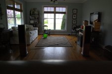
Hardwood floors?
Rug on floors paintings on walls. Pretty boxes in room corners. These back ported multiway a crest so many nasty room modes and phase issues. Got the pulled meter from wall, thrird of the way into the room just to keep bass from sounding like movie theatre.
Rug on floors paintings on walls. Pretty boxes in room corners. These back ported multiway a crest so many nasty room modes and phase issues. Got the pulled meter from wall, thrird of the way into the room just to keep bass from sounding like movie theatre.
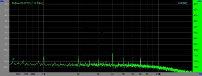
Looked at this some more, as I was having trouble with it, mentally. Not shocking for me, but it was happening all the same. THen it hit me. If you look at the first picture with just the Funny^6 hooked up, youll notice that you have 2-6K harmonics apparent with just hook up. I would say these are issues with setup and other noise stuff in the test circuit. NOw if you look at the 1W measurement, youll notice that 4-7K harmonics do not change, with only 2K and 3K rising. I think probably a better way to get anidea of sitortion of circuit is to assume that the existing distortion levels in the test circuit could be extracted out of the final results. If you do so, what you get is 2K and 3K that are very close, with slight edge to 2K and everything above that is non issue, as it was present with no signal passing through amp and test rig. All the sudden, it makes more sense.
Attachments
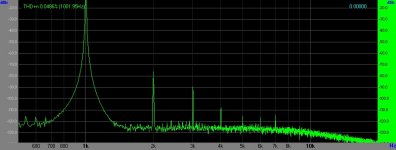
befire making any further measurements , you must sort your setup ; it seems you have both termination and software calibrating issues , looking at mute F6 FFT
I'm no expert , but that I know
however , short Skype session with someone who knows his drek , regarding PC testing , will have this things sorted
I'm no expert , but that I know
however , short Skype session with someone who knows his drek , regarding PC testing , will have this things sorted
This measurement maybe useful. Apply identical input signals so as to get identical 1 W power outputs in order to simulate distortion cancellation; or common mode rejection.befire making any further measurements , you must sort your setup ; it seems you have both termination and software calibrating issues , looking at mute F6 FFT
I'm no expert , but that I know
however , short Skype session with someone who knows his drek , regarding PC testing , will have this things sorted
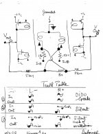
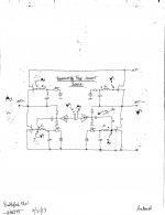
Zen Mod. I show a hand-drawn schematic from your post #193. I grounded the center point of the conjoined transformer primaries to simplify the analysis. Below the schematic is its performance Truth Table. It correlates the phase of signals on the transformers' primaries with their corresponding amps' power outputs.Buzzzz
you can make it quickie , as this one , for test (THD is scary) :
(feedback resistor values are preliminary ; buffers missing on sch , but must have)
Please clarify this question. Are the junctions of the 180 Ohm resistors with the primary windings Summing Nodes? Case 1 [DIDO] shows that these nodes are actually summing; or the signals across the 180 Ohm resistors are out of phase. Not so for Cases 2 and 3; which may be seen as positive feedback and thus a possible instability. For example Case3
- Initially, the input signals and at the summing junctions are equal to zero. The IN + and IN - are essentially grounded.
- Suppose the left amp develops a spurious oscillation which appears at its output [Vol].
- This Vol is routed to the summing junction of the right amp.
- The resultant right power output signal [Vor] is in phase with the original left power output signal [great news of rejection or cancellation of distortion]
- Vor is next routed to the summing junction of the left amp.
- It is amplified and generates a power output signal which augments the phase and amplitude of the parent oscillation.
- This feedback is further exacerbated with additional iterations
- This is positive feedback to possibly cause oscillation as an undesired side effect.
Attachments
Problem with Babelfish Bal F6
Zen Mod. Unfortunately it is serious. It was detected by analysis when the amp inputs [In+ and In -] are driven with differential signals. The voltage drop across the two transformer windings of the right amp [Vr] is equal in amplitude to the voltage drop across the other two transformer windings of the left amp [Vl]. But; Vr and Vl are 180 degrees out of phase with each other. Thus, they self destruct partially or fully in the common core of the transformer. A picture is attached.
Best regards.
Attachments
Antoinel, I am impressed with your investigative nature and thoroughness, but I believe you need to be patient and wait. I am not saying ZM is right or wrong, but I would bet on right. I think you are looking at this through SUSY, cross coupled eyes. There are a number of ways to skin a cat, as Nelson says. It will take some time to flesh out, and while I think sims are awesome, I don't have time to learn them. For me, it is building and testing. What is your opinion on fact that Funny^6 did not cancel 2k, like most balanced amps. Is it not balanced? Truth Is, I don't know. It will take further investigation.
Hardwood floors?
Rug on floors paintings on walls. Pretty boxes in room corners. These back ported multiway a crest so many nasty room modes and phase issues. Got the pulled meter from wall, thrird of the way into the room just to keep bass from sounding like movie theatre.
Old fashioned under-carpet felt hidden behind pictures can help; so can similar material in the pretty boxes, behind furniture etc.
Last edited:
Antoinel, I am impressed with your investigative nature and thoroughness, but I believe you need to be patient and wait. I am not saying ZM is right or wrong, but I would bet on right. I think you are looking at this through SUSY, cross coupled eyes. There are a number of ways to skin a cat, as Nelson says. It will take some time to flesh out, and while I think sims are awesome, I don't have time to learn them. For me, it is building and testing. What is your opinion on fact that Funny^6 did not cancel 2k, like most balanced amps. Is it not balanced? Truth Is, I don't know. It will take further investigation.
buzzforb. Your thread, accomplishment [Funny^6] and Zen Mod's posts got me excited and engaged in this thread. This is interesting stuff. I hope that my analyses todate are left field; but here is the flip side to what I have done which was to raise a concern flag [or to care] where needed. Unravel the good and bad in a schematic and then turn my back to it [and its writer], sit on it and ignore its consequences [time and money] on its owner.
Funny^6 is in your capable hands. It is based on a great sounding amp diyF6. Fortunately, I am not qualified to comment on your subjective and objective measurements. My role was to analyse it and inform to give a rounded background picture.
Best regards.
I know what you mean, but my point is this. Would you have expecxted the results shown from Funny^6? I am not qualified either, but i do have a fully functional Funny^6 that has shown no evidence of stablity or other issues. Fotunately, there are not a lot of people jumping on board to build this, so we have a safety margin
Zen Mod. I show a hand-drawn schematic from your post #193. I grounded the center point of the conjoined transformer primaries to simplify the analysis......
catch is ......... that I didn't drew that point grounded ;
repeat analysis as I drew it
Zen Mod. Unfortunately it is serious.......
sorry - I'm not following you with this ; wrestling with replaced mobo , just installed system and picking things from backup
- Status
- This old topic is closed. If you want to reopen this topic, contact a moderator using the "Report Post" button.
- Home
- Amplifiers
- Pass Labs
- Funny ^6